Chapter 4: Programming Techniques
This section describes some techniques other than macros which may be of help to the programmer.
Branch Tables Pseudo-Subroutine
Suppose a program consists of several separate routines, any of which may be executed depending upon some initial condition (such as a number passed in a register). One way to code this would be to check each condition sequentially and branch to the routines accordingly as follows:
CONDITION = CONDITION 1?
IF YES BRANCH TO ROUTINE 1
CONDITION = CONDITION 2?
IF YES BRANCH TO ROUTINE 2
    .
    .
    .
BRANCH TO ROUTINE N
A sequence as above is inefficient, and can be improved by using a branch table.
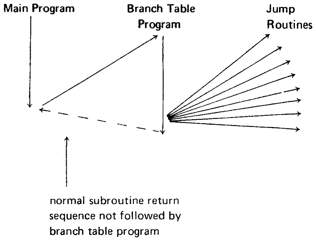
The logic at the beginning of the branch table program computes a pointer into the branch table. The branch table itself consists of a list of starting addresses for the routines to be branched to. Using the pointer, the branch table program loads the selected routine’s starting address into the address bytes of a jump instruction, then executes the jump. For example, consider a program that executes one of eight routines depending on which bit of the accumulator is set:
Jump to routine 1 if the accumulator holds 00000001
  "  "     "    2 "   "       "        "   00000010
  "  "     "    3 "   "       "        "   00000100
  "  "     "    4 "   "       "        "   00001000
  "  "     "    5 "   "       "        "   00010000
  "  "     "    6 "   "       "        "   00100000
  "  "     "    7 "   "       "        "   01000000
  "  "     "    8 "   "       "        "   10000000
A program that provides the above logic is given at the end of this section. The program is termed a “pseudo-subroutine” because it is treated as a subroutine by the programmer (i.e., it appears just once in memory), but it is entered via a regular JUMP instruction rather than via a CALL instruction. This is possible because the branch routine controls subsequent execution, and will never return to the instruction following the call:
Label   Code    Operand
START:  LXI     H,BTBL      ; Registers H and L will
                            ; point to branch table.
GTBIT:  RAR
        JC      GETAD
        INX     H           ; (H,L)=(H,L)+2 to
        INX     H           ; point to next address
                            ; in branch table.
        JMP     GTBIT
GETAD:  MOV     E,M         ; A one bit was found.
        INX     H           ; Get address in D and
                            ; E.
        MOV     D,M
        XCHG                ; Exchange D and E
                            ; with H and L.
        PCHL                ; Jump to routine
                            ; address.
  .
  .
BTBL:   DW      ROUT1       ; Branch table. Each
        DW      ROUT2       ; entry is a two-byte
                            ; address
        DW      ROUT3       ; held least significant
        DW      ROUT4       ; byte first.
        DW      ROUT5
        DW      ROUT6
        DW      ROUT7
        DW      ROUT8
The control routine at START uses the H and L registers as a pointer into the branch table (BTBL) corresponding to the bit of the accumulator that is set. The routine at GETAD then transfers the address held in the corresponding branch table entry to the H and L registers via the D and E registers, and then uses a PCHL instruction, thus transferring control to the selected routine.
Subroutines
Frequently, a group of instructions must be repeated many times in a program. As we have seen in Chapter 3, it is sometimes helpful to define a macro to produce these groups. If a macro becomes too lengthy or must be repeated many times, however, better economy can be obtained by using subroutines.
A subroutine is coded like any other group of assembly language statements, and is referred to by its name, which is the label of the first instruction. The programmer references a subroutine by writing its name in the operand field of a CALL instruction. When the CALL is executed, the address of the next sequential instruction after the CALL is pushed onto the stack (see the section on the Stack Pointer in Chapter 1), and program execution proceeds with the first instruction of the subroutine. When the subroutine has completed its work, a RETURN instruction is executed, which causes the top address in the stack to be popped into the program counter, causing program execution to continue with the instruction following the CALL. Thus, one copy of a subroutine may be called from many different points in memory, preventing duplication of code.
Example:
Subroutine MINC increments a 16-bit number held least-significant-byte first in two consecutive memory locations, and then returns to the instruction following the last CALL statement executed. The address of the number to be incremented is passed in the H and L registers.
Label   Code    Operand     Comment
MINC:   INR     M           ; Increment low-order byte
        RNZ                 ; If non-zero, return to
                            ; calling routine
        INX     H           ; Address high-order byte
        INR     M           ; Increment high-order byte
        RET                 ; Return unconditionally
Assume MINC appears in the following program:
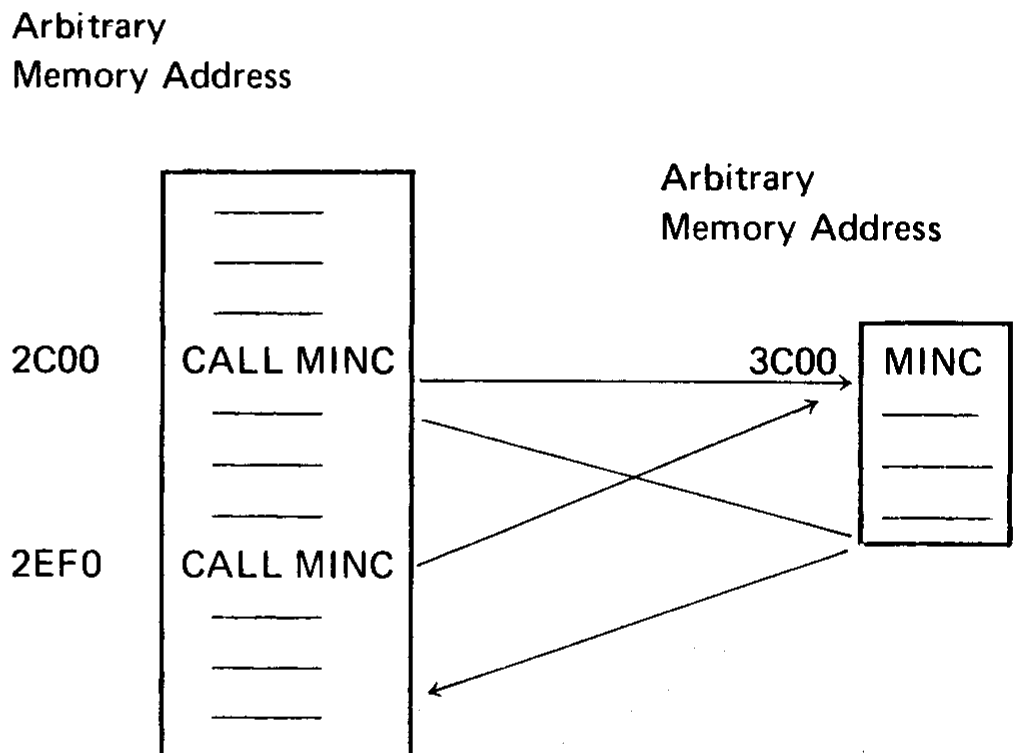
When the first call is executed, address 2C03H is pushed onto the stack indicated by the stack pointer, and control is transferred to 3C00H. Execution of either RETURN statement in MINC will cause the top entry to be popped off the stack into the program counter, causing execution to continue at 2C03H (since the CALL statement is three bytes long).
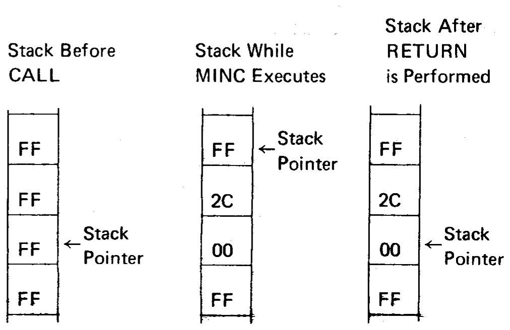
Todo
The stack diagram is transcribed as printed (scans/page-55.png). It
shows the pushed return address as bytes 2C and 00 (2C00H), but the text
says 2C03H is pushed. The low byte should probably be 03.
When the second call is executed, address 2EF3H is pushed onto the stack, and control is again transferred to MINC. This time, either RETURN instruction will cause execution to resume at 2EF3H.
Note that MINC could have called another subroutine during its execution, causing another address to be pushed onto the stack. This can occur as many times as necessary, limited only by the size of memory available for the stack.
Note also that any subroutine could push data onto the stack for temporary storage without affecting the call and return sequences as long as the same amount of data is popped off the stack before executing a RETURN statement.
Transferring Data To Subroutines
A subroutine often requires data to perform its operations. In the simplest case, this data may be transferred in one or more registers. Subroutine MINC in the last section, for example, receives the memory address which it requires in the H and L registers.
Sometimes it is more convenient and economical to let the subroutine load its own registers. One way to do this is to place a list of the required data (called a parameter list) in some data area of memory, and pass the address of this list to the subroutine in the H and L registers.
For example, the subroutine ADSUB expects the address of a three-byte parameter list in the H and L registers. It adds the first and second bytes of the list, and stores the result in the third byte of the list:
Label   Code    Operand     Comment
        LXI     H,PLIST     ; Load H and L with
                            ; addresses of the param-
                            ; eter list
        CALL    ADSUB       ; Call the subroutine
RET1:   --
  .
PLIST:  DB      6           ; First number to be added
        DB      8           ; Second number to be
                            ; added
        DS      1           ; Result will be stored here
  .
        LXI     H,LIST2     ; Load H and L registers
        CALL    ADSUB       ; for another call to ADSUB
RET2:   --
  .
LIST2:  DB      10
        DB      35
        DS      1
  .
ADSUB:  MOV     A,M         ; Get first parameter
        INX     H           ; Increment memory
                            ; address
        MOV     B,M         ; Get second parameter
        ADD     B           ; Add first to second
        INX     H           ; Increment memory
                            ; address
        MOV     M,A         ; Store result at third
                            ; parameter store
        RET                 ; Return unconditionally
The first time ADSUB is called, it loads the A and B registers from PLIST and PLIST+1 respectively, adds them, and stores the result in PLIST+2. Return is then made to the instruction at RET1.
First call to ADSUB:
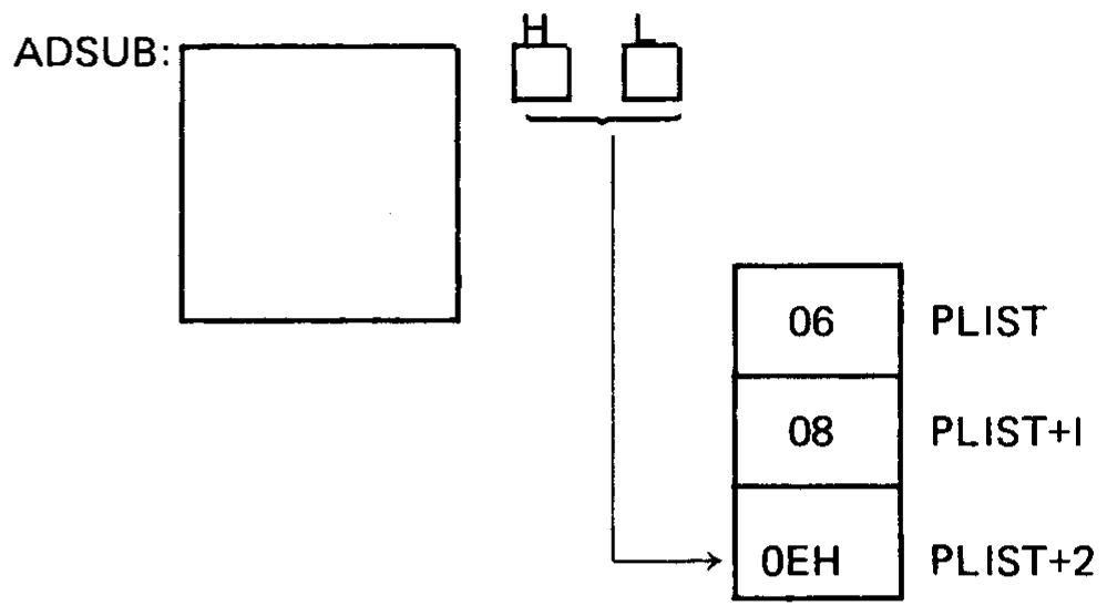
The second time ADSUB is called, the H and L registers point to the parameter list LIST2. The A and B registers are loaded with 10 and 35 respectively, and the sum is stored at LIST2 + 2. Return is then made to the instruction at RET2.
Second call to ADSUB:
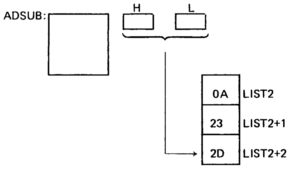
Note that the parameter lists PLIST and LIST2 could appear anywhere in memory without altering the results produced by ADSUB.
This approach does have its limitations, however. As coded, ADSUB must receive a list of two and only two numbers to be added, and they must be contiguous in memory. Suppose we wanted a subroutine (GENAD) which would add an arbitrary number of bytes, located anywhere in memory, and leave the sum in the accumulator.
This can be done by passing the subroutine a parameter list which is a list of addresses of parameters, rather than the parameters themselves, and signifying the end of the parameter list by a number whose first byte is FFH (assuming that no parameters will be stored above address FF00H).
Call to GENAD:
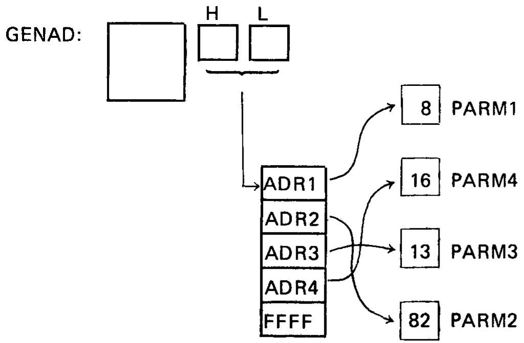
Todo
The GENAD diagram (scans/page-57.png) shows PARM1 = 8, but the program
below defines PARM1: DB 6. This inconsistency is in the original.
As implemented below, GENAD saves the current sum (beginning with zero) in the C register. It then loads the address of the first parameter into the D and E registers. If this address is greater than or equal to FF00H, it reloads the accumulator with the sum held in the C register and returns to the calling routine. Otherwise, it loads the parameter into the accumulator and adds the sum in the C register to the accumulator. The routine then loops back to pick up the remaining parameters.
Label   Code    Operand     Comment
        LXI     H,PLIST     ; Calling program
        CALL    GENAD
  .
PLIST:  DW      PARM1       ; List of parameter addresses
        DW      PARM2
        DW      PARM3
        DW      PARM4
        DW      0FFFFH      ; Terminator
  .
PARM1:  DB      6
PARM4:  DB      16
  .
PARM3:  DB      13
  .
PARM2:  DB      82
  .
GENAD:  XRA     A           ; Clear accumulator
LOOP:   MOV     C,A         ; Save current total in C
        MOV     E,M         ; Get low order address byte
                            ; of first parameter
        INX     H
        MOV     A,M         ; Get high order address byte
                            ; of first parameter
        CPI     0FFH        ; Compare to FFH
        JZ      BACK        ; If equal, routine is complete
        MOV     D,A         ; D and E now address parameter
        LDAX    D           ; Load accumulator with parameter
        ADD     C           ; Add previous total
        INX     H           ; Increment H and L to point
                            ; to next parameter address
        JMP     LOOP        ; Get next parameter
BACK:   MOV     A,C         ; Routine done--restore total
        RET                 ; Return to calling routine
Note that GENAD could add any combination of the parameters with no change to the parameters themselves.
The sequence:
        LXI     H,PLIST
        CALL    GENAD
  .
PLIST:  DW      PARM4
        DW      PARM1
        DW      0FFFFH
would cause PARM1 and PARM4 to be added, no matter where in memory they might be located (excluding addresses above FF00H).
Many variations of parameter passing are possible. For example, if it was necessary to allow parameters to be stored at any address, a calling program could pass the total number of parameters as the first parameter; the subroutine would load this first parameter into a register and use it as a counter to determine when all parameters had been accepted.
Software Multiply and Divide
The multiplication of two unsigned 8-bit data bytes may be accomplished by one of two techniques: repetitive addition, or use of a register shifting operation.
Repetitive addition provides the simplest, but slowest, form of multiplication. For example, 2AH·74H may be generated by adding 74H to the (initially zeroed) accumulator 2AH times.
Using shift operations provides faster multiplication. Shifting a byte left one bit is equivalent to multiplying by 2, and shifting a byte right one bit is equivalent to dividing by 2. The following process will produce the correct 2-byte result of multiplying a one byte multiplicand by a one byte multiplier:
Test the least significant bit of the multiplier. If zero, go to step b. If one, add the multiplicand to the most significant byte of the result.
Shift the entire two-byte result right one bit position.
Repeat steps a and b until all 8 bits of the multiplier have been tested.
For example, consider the multiplication:
2AH·3CH=9D8H
                                            HIGH-ORDER BYTE   LOW-ORDER BYTE
              MULTIPLIER    MULTIPLICAND    OF RESULT         OF RESULT

Start         00111100      00101010        00000000          00000000
Step 1 a  --------------------------------
       b                                    00000000          00000000
Step 2 a  --------------------------------
       b                                    00000000          00000000
Step 3 a  --------------------------------  00101010          00000000
       b                                    00010101          00000000
Step 4 a  --------------------------------  00111111          00000000
       b                                    00011111          10000000
Step 5 a  --------------------------------  01001001          10000000
       b                                    00100100          11000000
Step 6 a  --------------------------------  01001110          11000000
       b                                    00100111          01100000
Step 7 a  --------------------------------
       b                                    00010011          10110000
Step 8 a  --------------------------------
       b                                    00001001          11011000
Step 1: Test multiplier 0-bit; it is 0, so shift 16-bit result right one bit.
Step 2: Test multiplier 1-bit; it is 0, so shift 16-bit result right one bit.
Step 3: Test multiplier 2-bit; it is 1, so add 2AH to high-order byte of result and shift 16-bit result right one bit.
Step 4: Test multiplier 3-bit; it is 1, so add 2AH to high-order byte of result and shift 16-bit result right one bit.
Step 5: Test multiplier 4-bit; it is 1, so add 2AH to high-order byte of result and shift 16-bit result right one bit.
Step 6: Test multiplier 5-bit; it is 1, so add 2AH to high-order byte of result and shift 16-bit result right one bit.
Step 7: Test multiplier 6-bit; it is 0, so shift 16-bit result right one bit.
Step 8: Test multiplier 7-bit; it is 0, so shift 16-bit result right one bit.
The result produced is 09D8.
The process works for the following reason:
The result of any multiplication may be written:
where BIT0 through BIT8 are the bits of the multiplier (each equal to zero or one), and MCND is the multiplicand.
For example:
MULTIPLICAND        MULTIPLIER
  00001010     ·     00000101    =

0·0AH·2^7 + 0·0AH·2^6 + 0·0AH·2^5 + 0·0AH·2^4 +
0·0AH·2^3 + 1·0AH·2^2 + 0·0AH·2^1 + 1·0AH·2^0 =

00101000 + 00001010 = 00110010 = 50 (decimal)
Adding the multiplicand to the high-order byte of the result is the same as adding MCND·28 to the full 16-bit result; shifting the 16-bit result one position to the right is equivalent to multiplying the result by 2-1 (dividing by 2).
Therefore, step one above produces:
Step two produces:
And so on, until step eight produces:
which is equivalent to Equation 1 above, and therefore is the correct result.
Since the multiplication routine described above uses a number of important programming techniques, a sample program is given with comments.
The program uses the B register to hold the most significant byte of the result, and the C register to hold the least significant byte of the result.
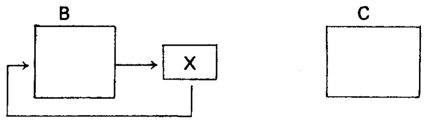
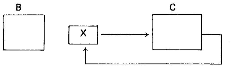
The 16-bit right shift of the result is performed by two rotate-right-through-carry instructions:
Zero carry and then rotate B
Then rotate C to complete the shift
Register D holds the multiplicand, and register C originally holds the multiplier.
MULT:   MVI     B,0         ; Initialize most significant byte
                            ; of result
        MVI     E,9         ; Bit counter
MULT0:  MOV     A,C         ; Rotate least significant bit of
        RAR                 ; multiplier to carry and shift
        MOV     C,A         ; low-order byte of result
        DCR     E
        JZ      DONE        ; Exit if complete
        MOV     A,B
        JNC     MULT1
        ADD     D           ; Add multiplicand to high-
                            ; order byte of result if bit
                            ; was a one
MULT1:  RAR                 ; Carry=0 here; shift high-
                            ; order byte of result
        MOV     B,A
        JMP     MULT0
DONE:
An analogous procedure is used to divide an unsigned 16-bit number by an unsigned 8-bit number. Here, the process involves subtraction rather than addition, and rotate-left instructions instead of rotate-right instructions.
The program uses the B and C registers to hold the most and least significant byte of the dividend respectively, and the D register to hold the divisor. The 8-bit quotient is generated in the C register, and the remainder is generated in the B register.
DIV:    MVI     E,9         ; Bit counter
        MOV     A,B
DIV0:   MOV     B,A
        MOV     A,C         ; Rotate carry into C
                            ; register; rotate next
                            ; most significant bit
                            ; to carry
        MOV     C,A
        DCR     E
        JZ      DIV2
        MOV     A,B         ; Rotate most significant
        RAL                 ; bit to high-order
        JNC     DIV1        ; quotient
        SUB     D           ; Subtract divisor & loop
        JMP     DIV0
DIV1:   SUB     D           ; Subtract divisor. If
                            ; less than high-order
        JNC     DIV0        ; quotient, loop.
        ADD     D           ; Otherwise, add it back
        JMP     DIV0
DIV2:   RAL
        MOV     E,A
        MVI     A,0FFH      ; Complement the quotient
        XRA     C
        MOV     C,A
        MOV     A,E
        RAR
DONE:
Todo
The DIV listing is transcribed as printed (scans/page-60.png). The
comment on MOV A,C (“Rotate carry into C register; rotate next most
significant bit to carry”) describes a rotate, but no RAL follows it in
the listing. This may be a misprint in the original.
Multibyte Addition and Subtraction
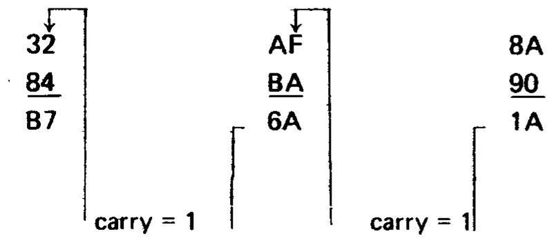
The carry bit and the ADC (add with carry) instructions may be used to add unsigned data quantities of arbitrary length. Consider the following addition of two three-byte unsigned hexadecimal numbers:
  32AF8A
+ 84BA90
  ------
  B76A1A
This addition may be performed on the 8080 by adding the two low-order bytes of the numbers, then adding the resulting carry to the two next-higher-order bytes, and so on:
The following routine will perform this multibyte addition, making these assumptions:
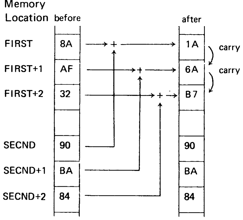
The C register holds the length of each number to be added (in this case, 3).
The numbers to be added are stored from low-order byte to high-order byte beginning at memory locations FIRST and SECND, respectively.
The result will be stored from low-order byte to high-order byte beginning at memory location FIRST, replacing the original contents of these locations.
Label   Code    Operand     Comment
MADD:   LXI     B,FIRST     ; B and C address FIRST
        LXI     H,SECND     ; H and L address SECND
        XRA     A           ; Clear carry bit
LOOP:   LDAX    B           ; Load byte of FIRST
        ADC     M           ; Add byte of SECND
                            ; with carry
        STAX    B           ; Store result at FIRST
        DCR     C           ; Done if C = 0
        JZ      DONE
        INX     B           ; Point to next byte of
                            ; FIRST
        INX     H           ; Point to next byte of
                            ; SECND
        JMP     LOOP        ; Add next two bytes
DONE:   --
  .
FIRST:  DB      90H
        DB      0BAH
        DB      84H
SECND:  DB      8AH
        DB      0AFH
        DB      32H
Since none of the instructions in the program loop affect the carry bit except ADC, the addition with carry will proceed correctly.
When location DONE is reached, bytes FIRST through FIRST+2 will contain 1A6AB7, which is the sum shown at the beginning of this section arranged from low-order to high-order byte.
The carry (or borrow) bit and the SBB (subtract with borrow) instruction may be used to subtract unsigned data quantities of arbitrary length. Consider the following subtraction of two two-byte unsigned hexadecimal numbers:
  1301
- 0503
  ----
  0DFE
This subtraction may be performed on the 8080 by subtracting the two low-order bytes of the numbers, then using the resulting carry bit to adjust the difference of the two higher-order bytes if a borrow occurred (by using the SBB instruction).
Low-order subtraction (carry bit = 0 indicating no borrow):
  00000001 = 01H
  11111101 = -(03H+carry)
  --------
0 11111110 = 0FEH, the low-order result
|
+--> carry out = 0, setting the Carry bit = 1, indicating a borrow
High-order subtraction:
  00010011 = 13H
  11111010 = -(05H+carry)
  --------
1 00001101
|
+--> carry out = 1, resetting the Carry bit indicating no borrow
Whenever a borrow has occurred, the SBB instruction increments the subtrahend by one, which is equivalent to borrowing one from the minuend.
In order to create a multibyte subtraction routine, it is necessary only to duplicate the multibyte addition routine of this section, changing the ADC instruction to an SBB instruction. The program will then subtract the number beginning at SECND from the number beginning at FIRST, placing the result at FIRST.
Decimal Addition
Any 4-bit data quantity may be treated as a decimal number as long as it represents one of the decimal digits from 0 through 9, and does not contain any of the bit patterns representing the hexadecimal digits A through F. In order to preserve this decimal interpretation when performing addition, the value 6 must be added to the 4-bit quantity whenever the addition produces a result between 10 and 15. This is because each 4-bit data quantity can hold 6 more combinations of bits than there are decimal digits.
Decimal addition is performed on the 8080 by letting each 8-bit byte represent two 4-bit decimal digits. The bytes are summed in the accumulator in standard fashion, and the DAA (decimal adjust accumulator) instruction is then used as in Section 3, to convert the 8-bit binary result to the correct representation of 2 decimal digits. The settings of the carry and auxiliary carry bits also affect the operation of the DAA, permitting the addition of decimal numbers longer than two digits.
To perform the decimal addition:
  2985
+ 4936
  ----
  7921
the process works as follows:
Clear the Carry and add the two lowest-order digits of each number (remember that each 2 decimal digits are represented by one byte).
   85 = 10000101B
   36 = 00110110B
carry =        0
       ---------
     0 10111011B
     |     |
     |     +--> Auxiliary Carry = 0
     +--> Carry = 0
The accumulator now contains BBH.
Perform a DAA operation. Since the rightmost four bits are ≥ 10D, 6 will be added to the accumulator.
Accumulator = 10111011B
          6 =     0110B
              ---------
              11000001B
Since the leftmost 4 bits are now ≥ 10, 6 will be added to these bits, setting the Carry bit.
Accumulator =   11000001B
          6 =   0110    B
              ----------
              1 00100001B
              |
              +--> Carry bit = 1
The accumulator now contains 21H. Store these two digits.
Add the next group of two digits:
   29 = 00101001B
   49 = 01001001B
carry =        1
       ---------
     0 01110011B
     |     |
     |     +--> Auxiliary Carry = 1
     +--> Carry = 0
The accumulator now contains 73H.
Perform a DAA operation. Since the Auxiliary Carry bit is set, 6 will be added to the accumulator.
Accumulator =   01110011B
          6 =       0110B
              ----------
              0 01111001B
              |
              +--> carry bit = 0
Since the leftmost 4 bits are < 10 and the Carry bit is reset, no further action occurs.
Thus, the correct decimal result 7921 is generated in two bytes.
A routine which adds decimal numbers, then, is exactly analogous to the multibyte addition routine MADD of the last section, and may be produced by inserting the instruction DAA after the ADC M instruction of that example.
Each iteration of the program loop will add two decimal digits (one byte) of the numbers.
Decimal Subtraction
Each 4-bit data quantity may be treated as a decimal number as long as it represents one of the decimal digits 0 through 9. The DAA (decimal adjust accumulator) instruction may be used to permit subtraction of one byte (representing a 2-digit decimal number) from another, generating a 2-digit decimal result. In fact, the DAA permits subtraction of multidigit decimal numbers.
The process consists of generating the hundred’s complement of the subtrahend digit (the difference between the subtrahend digit and 100 decimal), and adding the result to the minuend digit. For instance, to subtract 34D from 56D, the hundred’s complement of 34D (100D-34D=66D) is added to 56D, producing 122D, which when truncated to 8 bits gives 22D, the correct result. If a borrow was generated by the previous subtraction, the 99’s complement of the subtrahend digit is produced to compensate for the borrow.
In detail, the procedure for subtracting one multi-digit decimal from another is as follows:
Set the Carry bit = 1 indicating no borrow.
Load the accumulator with 99H, representing the number 99 decimal.
Add zero to the accumulator with carry, producing either 99H or 9AH, and resetting the Carry bit.
Subtract the subtrahend digits from the accumulator, producing either the 99’s or 100’s complement.
Add the minuend digits to the accumulator.
Use the DAA instruction to make sure the result in the accumulator is in decimal format, and to indicate a borrow in the Carry bit if one occurred.
Save this result.
If there are more digits to subtract, go to step 2. Otherwise, stop.
Example:
Perform the decimal subtraction:
  4358D
- 1362D
  -----
  2996D
Set carry = 1.
Load accumulator with 99H.
Add zero with carry to the accumulator, producing 9AH.
Accumulator = 10011001B
          0 = 00000000B
      Carry =        1
              ---------
              10011010B = 9AH
Subtract the subtrahend digits 62H from the accumulator.
Accumulator =   10011010B
       -62H =   10011110B
              ----------
              1 00111000B
Add the minuend digits 58H to the accumulator.
Accumulator =   00111000B
        58H =   01011000B
              ----------
              0 10010000B = 90H
              |     |
              |     +--> Auxiliary Carry = 1
              +--> Carry = 0
DAA converts accumulator to 96H (since Auxiliary Carry = 1) and leaves Carry bit = 0 indicating that a borrow occurred.
Load accumulator with 99H.
Add zero with carry to accumulator, leaving accumulator = 99H.
Subtract the subtrahend digits 13H from the accumulator.
Accumulator =   10011001B
       -13H =   11101101B
              ----------
              1 10000110B
Add the minuend digits 43H to the accumulator.
Accumulator =   10000110B
        43H =   01000011B
              ----------
              0 11001001B = C9H
              |     |
              |     +--> Auxiliary Carry = 0
              +--> Carry = 0
DAA converts accumulator to 29H and sets the carry bit = 1, indicating no borrow occurred.
Therefore, the result of subtracting 1362D from 4358D is 2996D.
Note
In the scan (scans/page-62.png), “-62H” and “-13H” are printed as
62H and 13H with a bar over them (complement notation).
The following subroutine will subtract one 16-digit decimal number from another using the following assumptions:
The minuend is stored least significant (2) digits first beginning at location MINU.
The subtrahend is stored least significant (2) digits first beginning at location SBTRA.
The result will be stored least significant (2) digits first, replacing the minuend.
Label   Code    Operand     Comment
DSUB:   LXI     D,MINU      ; D and E address minuend
        LXI     H,SBTRA     ; H and L address subtra-
                            ; hend
        MVI     C,8         ; Each loop subtracts 2
                            ; digits (one byte),
                            ; therefore program will
                            ; subtract 16 digits.
        STC                 ; Set Carry indicating
                            ; no borrow
LOOP:   MVI     A,99H       ; Load accumulator
                            ; with 99H.
        ACI     0           ; Add zero with Carry
        SUB     M           ; Produce complement
                            ; of subtrahend
        XCHG                ; Switch D and E with
                            ; H and L
        ADD     M           ; Add minuend
        DAA                 ; Decimal adjust
                            ; accumulator
        MOV     M,A         ; Store result
        XCHG                ; Reswitch D and E
                            ; with H and L
        DCR     C           ; Done if C = 0
        JZ      DONE
        INX     D           ; Address next byte
                            ; of minuend
        INX     H           ; Address next byte
                            ; of subtrahend
        JMP     LOOP        ; Get next 2 decimal digits
DONE:   NOP
Altering Macro Expansions
This section describes how a macro may be written such that identical references to the macro produce different expansions. As a useful example of this, consider a macro SBMAC which needs to call a subroutine SUBR to perform its function. One way to provide the macro with the necessary subroutine would be to include a separate copy of the subroutine in any program which contains the macro. A better method is to let the macro itself generate the subroutine during the first macro expansion, but skip the generation of the subroutine on any subsequent expansion. This may be accomplished as follows:
Consider the following program section which consists of one global set statement and the definition of SBMAC (dashes indicate those assembly language statements necessary to the program, but irrelevant to this discussion):
Label   Code    Operand
FIRST   SET     0FFH
SBMAC   MACRO
        --
        --
        CALL    SUBR
        --
        --
        IF      FIRST
FIRST   SET     0
        JMP     OUT
SUBR::  --
        --
        RET
OUT:    NOP
        ENDIF
        ENDM
The symbol FIRST is set to FFH, then the macro SBMAC is defined.
The first time SBMAC is referenced, the expansion produced will be the following:
Label   Code    Operand
        SBMAC
        --
        --
        CALL    SUBR
        --
        --
        IF      FIRST
FIRST   SET     0
        JMP     OUT
SUBR:   --
        --
        RET
OUT:    NOP
Since FIRST is non-zero when encountered during this expansion, the statements between the IF and ENDIF are assembled into the program. The first statement thus assembled sets the value of FIRST to 0, while the remaining statements are the necessary subroutine SUBR and a jump around the subroutine. When this portion of the program is executed, the subroutine SUBR will be called, but program execution will not flow into the subroutine’s definition.
On any subsequent reference to SBMAC in the program, however, the following expansion will be produced:
Label   Code    Operand
        SBMAC
        --
        --
        CALL    SUBR
        --
        --
        IF      FIRST
Since FIRST is now equal to zero, the IF statement ends the macro expansion and does not cause the subroutine to be generated again. The label SUBR is known during this expansion because it was defined globally (followed by two colons in the definition).