Chapter 1: Computer Organization
This section provides the programmer with a functional overview of the 8080. Information is presented in this section at a level that provides a programmer with necessary background in order to write efficient programs.
To the programmer, the computer is represented as consisting of the following parts:
Seven working registers in which all data operations occur, and which provide one means for addressing memory.
Memory, which may hold program instructions or data and which must be addressed location by location in order to access stored information.
The program counter, whose contents indicate the next program instruction to be executed.
The stack pointer, a register which enables various portions of memory to be used as stacks. These in turn facilitate execution of subroutines and handling of interrupts as described later.
Input/Output, which is the interface between a program and the outside world.
Working Registers
The 8080 provides the programmer with an 8-bit accumulator and six additional 8-bit “scratchpad” registers.
These seven working registers are numbered and referenced via the integers 0, 1, 2, 3, 4, 5, and 7; by convention, these registers may also be accessed via the letters B, C, D, E, H, L, and A (for the accumulator), respectively.
Some 8080 operations reference the working registers in pairs referenced by the letters B, D, H and PSW. These correspondences are shown as follows:
Register Pair |
Registers Referenced |
|---|---|
B |
B and C (0 and 1) |
D |
D and E (2 and 3) |
H |
H and L (4 and 5) |
PSW |
See below |
Register pair PSW (Program Status Word) refers to register A (7) and a special byte which reflects the current status of the machine flags. This byte is described in detail in Chapter 2.
Memory
The 8080 can be used with read only memory, programmable read only memory and read/write memory. A program can cause data to be read from any type of memory, but can only cause data to be written into read/write memory.
The programmer visualizes memory as a sequence of bytes, each of which may store 8 bits (represented by two hexadecimal digits). Up to 65,536 bytes of memory may be present, and an individual memory byte is addressed by its sequential number from 0 to 65,535D=FFFFH, the largest number which can be represented by 16 bits.
The bits stored in a memory byte may represent the encoded form of an instruction or may be data, as described in Chapter 2 in the section on Data Statements.
Program Counter
The program counter is a 16 bit register which is accessible to the programmer and whose contents indicate the address of the next instruction to be executed as described in this chapter under Computer Program Representation in Memory.
Stack Pointer
A stack is an area of memory set aside by the programmer in which data or addresses are stored and retrieved by stack operations. Stack operations are performed by several of the 8080 instructions, and facilitate execution of subroutines and handling of program interrupts. The programmer specifies which addresses the stack operations will operate upon via a special accessible 16-bit register called the stack pointer.
Input/Output
To the 8080, the outside world consists of up to 256 input devices and 256 output devices. Each device communicates with the 8080 via data bytes sent to or received from the accumulator, and each device is assigned a number from 0 to 255 which is not under control of the programmer. The instructions which perform these data transmissions are described in Chapter 2 under Input/Output Instructions.
Computer Program Representation in Memory
A computer program consists of a sequence of instructions. Each instruction enables an elementary operation such as the movement of a data byte, an arithmetic or logical operation on a data byte, or a change in instruction execution sequence. Instructions are described individually in Chapter 2.
A program will be stored in memory as a sequence of bits which represent the instructions of the program, and which we will represent via hexadecimal digits. The memory address of the next instruction to be executed is held in the program counter. Just before each instruction is executed, the program counter is advanced to the address of the next sequential instruction. Program execution proceeds sequentially unless a transfer-of-control instruction (jump, call, or return) is executed, which causes the program counter to be set to a specified address. Execution then continues sequentially from this new address in memory.
Upon examining the contents of a memory byte, there is no way of telling whether the byte contains an encoded instruction or data. For example, the hexadecimal code 1FH has been selected to represent the instruction RAR (rotate the contents of the accumulator right through carry); thus, the value 1FH stored in a memory byte could either represent the instruction RAR, or it could represent the data value 1FH. It is up to the logic of a program to insure that data is not misinterpreted as an instruction code, but this is simply done as follows:
Every program has a starting memory address, which is the memory address of the byte holding the first instruction to be executed. Before the first instruction is executed, the program counter will automatically be advanced to address the next instruction to be executed, and this procedure will be repeated for every instruction in the program. 8080 instructions may require 1, 2, or 3 bytes to encode an instruction; in each case the program counter is automatically advanced to the start of the next instruction, as illustrated in Figure 1-1.
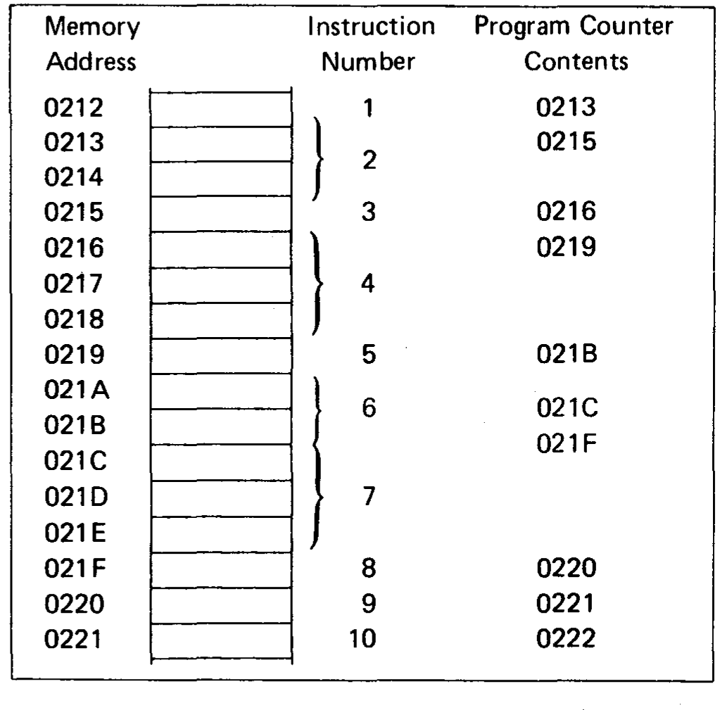
Figure 1-1. Automatic Advance of the Program Counter as Instructions Are Executed
In order to avoid errors, the programmer must be sure that a data byte does not follow an instruction when another instruction is expected. Referring to Figure 1-1, an instruction is expected in byte 021FH, since instruction 8 is to be executed after instruction 7. If byte 021FH held data, the program would not execute correctly. Therefore, when writing a program, do not store data in between adjacent instructions that are to be executed consecutively.
Note
If a program stores data into a location, that location should not normally appear among any program instructions. This is because user programs are (normally) executed from read-only memory, into which data cannot be stored.
A class of instructions (referred to as transfer-of-control instructions) cause program execution to branch to an instruction that may be anywhere in memory. The memory address specified by the transfer of control instruction must be the address of another instruction; if it is the address of a memory byte holding data, the program will not execute correctly. For example, referring to Figure 1-1, say instruction 4 specifies a jump to memory byte 021FH, and say instructions 5, 6, and 7 are replaced by data; then following execution of instruction 4, the program would execute correctly. But if, in error, instruction 4 specifies a jump to memory byte 021EH, an error would result, since this byte now holds data. Even if instructions 5, 6, and 7 were not replaced by data, a jump to memory byte 021EH would cause an error, since this is not the first byte of the instruction.
Upon reading Chapter 2, you will see that it is easy to avoid writing an assembly language program with jump instructions that have erroneous memory addresses. Information on this subject is given rather to help the programmer who is debugging programs by entering hexadecimal codes directly into memory.
Memory Addressing
By now it will have become apparent that addressing specific memory bytes constitutes an important part of any computer program; there are a number of ways in which this can be done, as described in the following subsections.
Direct Addressing
With direct addressing, an instruction supplies an exact memory address.
The instruction:
“Load the contents of memory address 1F2A into the accumulator”
is an example of an instruction using direct addressing, 1F2A being the direct address.
This would appear in memory as follows:
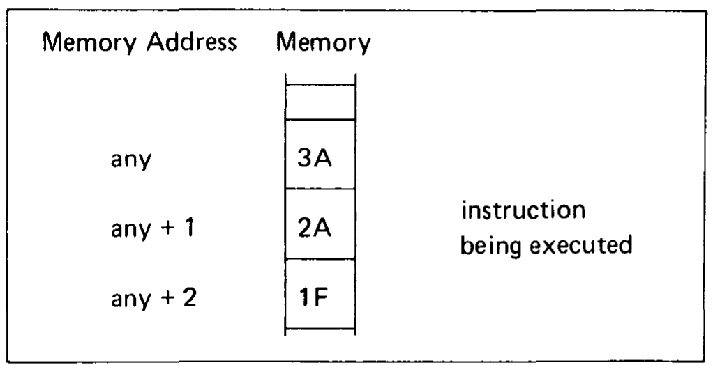
The instruction occupies three memory bytes, the second and third of which hold the direct address.
Register Pair Addressing
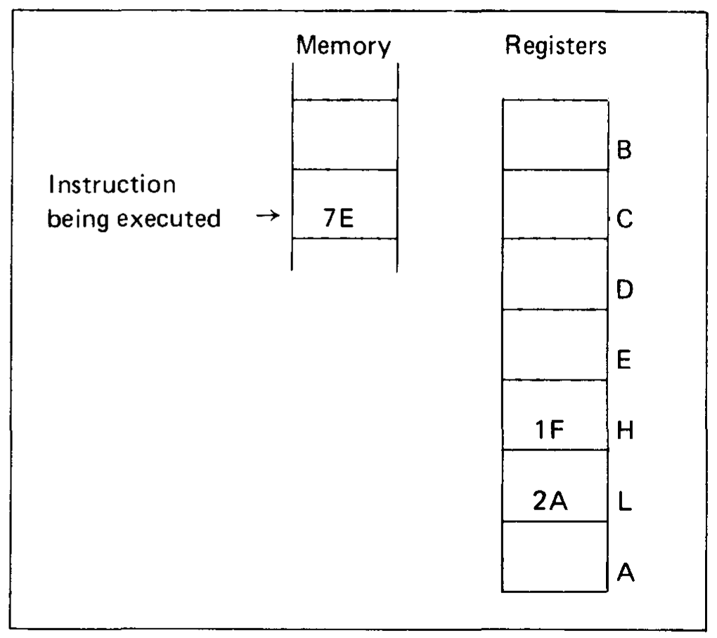
A memory address may be specified by the contents of a register pair. For almost all 8080 instructions, the H and L registers must be used. The H register contains the most significant 8 bits of the referenced address, and the L register contains the least significant 8 bits. A one byte instruction which will load the accumulator with the contents of memory byte 1F2A would appear as follows:
In addition, there are two 8080 instructions which use either the B and C registers or the D and E registers to address memory. As above, the first register of the pair holds the most significant 8 bits of the address, while the second register holds the least significant 8 bits. These instructions, STAX and LDAX, are described in Chapter 2 under Data Transfer Instructions.
Stack Pointer Addressing
Memory locations may be addressed via the 16-bit stack pointer register, as described below.
There are only two stack operations which may be performed; putting data into a stack is called a push, while retrieving data from a stack is called a pop.
Note
In order for stack push operations to operate, stacks must be located in read/write memory.
Stack Push Operation
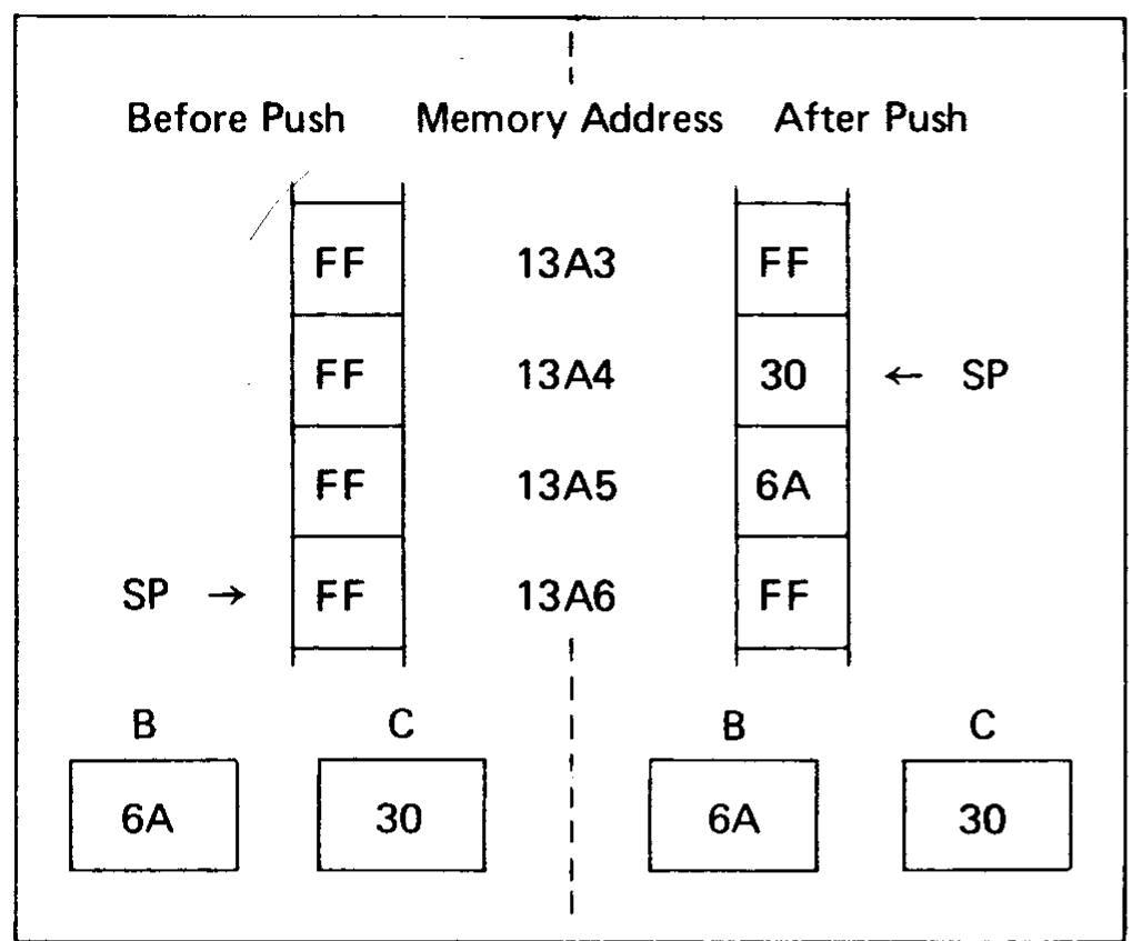
16 bits of data are transferred to a memory area (called a stack) from a register pair or the 16 bit program counter during any stack push operation. The addresses of the memory area which is to be accessed during a stack push operation are determined by using the stack pointer as follows:
The most significant 8 bits of data are stored at the memory address one less than the contents of the stack pointer.
The least significant 8 bits of data are stored at the memory address two less than the contents of the stack pointer.
The stack pointer is automatically decremented by two.
For example, suppose that the stack pointer contains the address 13A6H, register B contains 6AH, and register C contains 30H. Then a stack push of register pair B would operate as follows:
Stack Pop Operation
16 bits of data are transferred from a memory area (called a stack) to a register pair or the 16-bit program counter during any stack pop operation. The addresses of the memory area which is to be accessed during a stack pop operation are determined by using the stack pointer as follows:
The second register of the pair, or the least significant 8 bits of the program counter, are loaded from the memory address held in the stack pointer.
The first register of the pair, or the most significant 8 bits of the program counter, are loaded from the memory address one greater than the address held in the stack pointer.
The stack pointer is automatically incremented by two.
For example, suppose that the stack pointer contains the address 1508H, memory location 1508H contains 33H, and memory location 1509H contains 0BH. Then a stack pop into register pair H would operate as follows:
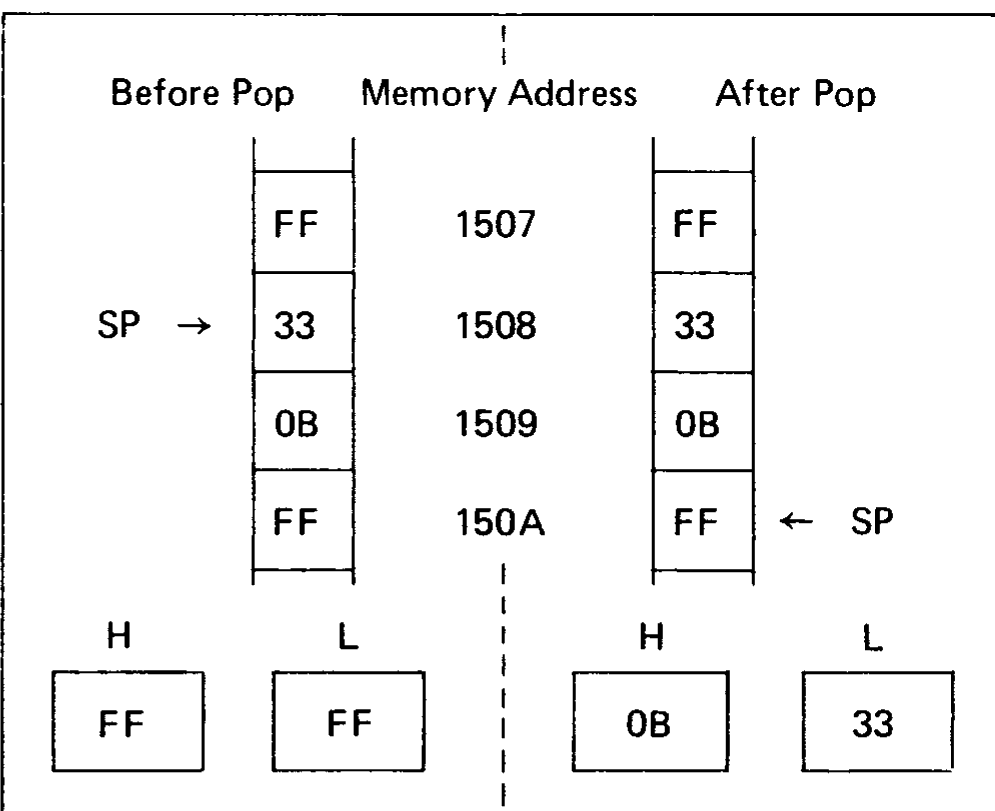
The programmer loads the stack pointer with any desired value by using the LXI instruction described in Chapter 2 under Load Register Pair-Immediate. The programmer must initialize the stack pointer before performing a stack operation, or erroneous results will occur.
Immediate Addressing
An immediate instruction is one that contains data. The following is an example of immediate addressing:
“Load the accumulator with the value 2AH.”
The above instruction would be coded in memory as follows:
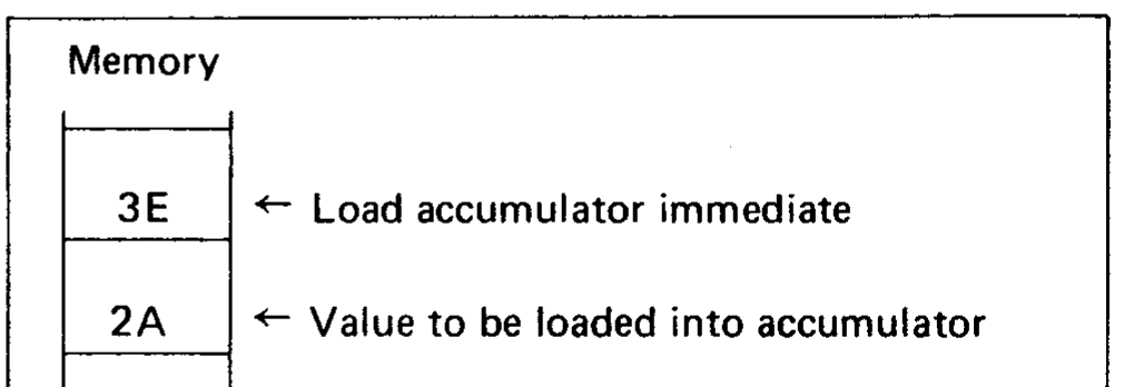
Immediate instructions do not reference memory; rather they contain data in the memory byte following the instruction code byte.
Subroutines and Use of the Stack for Addressing
Before understanding the purpose or effectiveness of the stack, it is necessary to understand the concept of a subroutine.
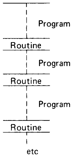
Consider a frequently used operation such as multiplication. The 8080 provides instructions to add one byte of data to another byte of data, but what if you wish to multiply these numbers? This will require a number of instructions to be executed in sequence. It is quite possible that this routine may be required many times within one program; to repeat the identical code every time it is needed is possible, but very wasteful of memory:
A more efficient means of accessing the routine would be to store it once, and find a way of accessing it when needed:
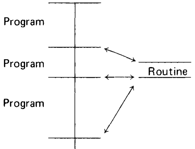
A frequently accessed routine such as the above is called a subroutine, and the 8080 provides instructions that call and return from subroutines.
When a subroutine is executed, the sequence of events may be depicted as follows:
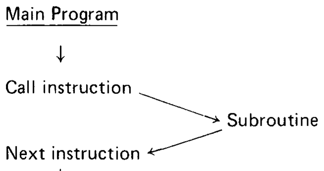
The arrows indicate the execution sequence.
When the “Call” instruction is executed, the address of the “next” instruction (that is, the address held in the program counter), is pushed onto the stack, and the subroutine is executed. The last executed instruction of a subroutine will usually be a “Return Instruction,” which pops an address off the stack into the program counter, and thus causes program execution to continue at the “Next” instruction as illustrated below:
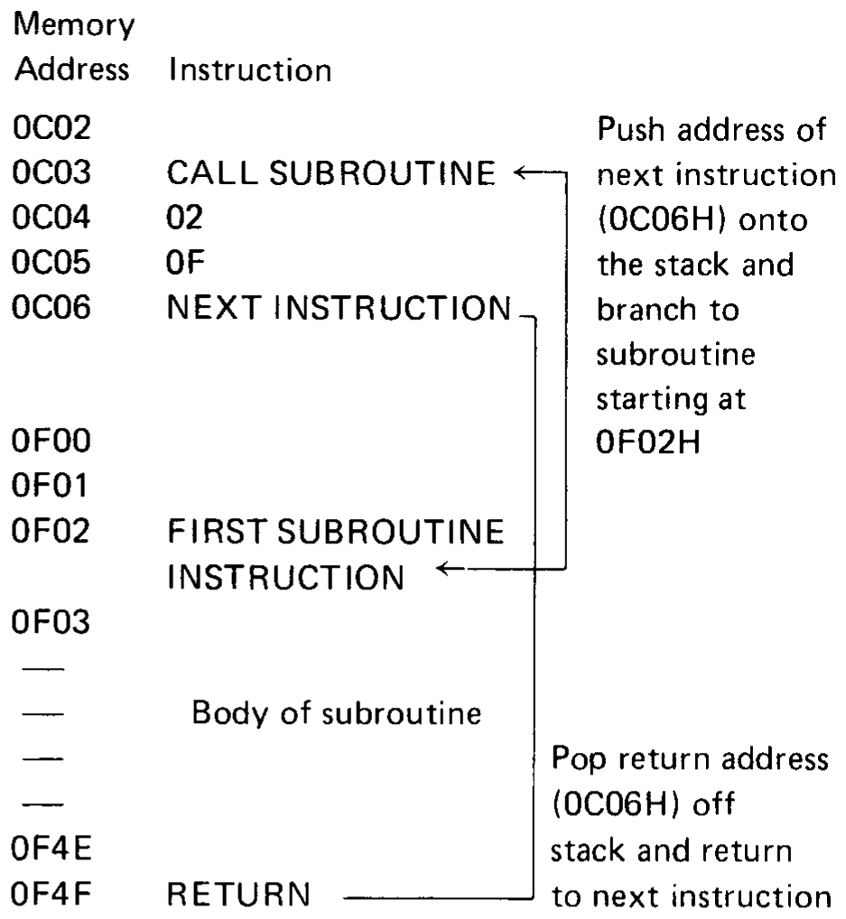
Subroutines may be nested up to any depth limited only by the amount of memory available for the stack. For example, the first subroutine could itself call some other subroutine and so on. An examination of the sequence of stack pushes and pops will show that the return path will always be identical to the call path, even if the same subroutine is called at more than one level.
Condition Bits
Five condition (or status) bits are provided by the 8080 to reflect the results of data operations. All but one of these bits (the auxiliary carry bit) may be tested by program instructions which affect subsequent program execution. The descriptions of individual instructions in Chapter 2 specify which condition bits are affected by the execution of the instruction, and whether the execution of the instruction is dependent in any way on prior status of condition bits.
In the following discussion of condition bits, “setting” a bit causes its value to be 1, while “resetting” a bit causes its value to be 0.
Carry Bit
The Carry bit is set and reset by certain data operations, and its status can be directly tested by a program. The operations which affect the Carry bit are addition, subtraction, rotate, and logical operations. For example, addition of two one-byte numbers can produce a carry out of the high-order bit:
Bit No.    7 6 5 4 3 2 1 0
  AE =     1 0 1 0 1 1 1 0
 +74 =     0 1 1 1 0 1 0 0
           ---------------
         1 0 0 1 0 0 0 1 0 = 22H
         |
         +--> Carry-out = 1, sets Carry Bit = 1
An addition operation that results in a carry out of the high-order bit will set the Carry bit; an addition operation that could have resulted in a carry out but did not will reset the Carry bit.
Note
Addition, subtraction, rotate, and logical operations follow different rules for setting and resetting the Carry bit. See Chapter 2 under Two’s Complement Representation and the individual instruction descriptions in Chapter 2 for details. The 8080 instructions which use the addition operation are ADD, ADC, ADI, ACI, and DAD. The instructions which use the subtraction operation are SUB, SBB, SUI, SBI, CMP, and CPI. Rotate operations are RAL, RAR, RLC, and RRC. Logical operations are ANA, ORA, XRA, ANI, ORI, and XRI.
Auxiliary Carry Bit
The Auxiliary Carry bit indicates carry out of bit 3. The state of the Auxiliary Carry bit cannot be directly tested by a program instruction and is present only to enable one instruction (DAA, described in Chapter 2) to perform its function. The following addition will reset the Carry bit and set the Auxiliary Carry bit:
Bit No.    7 6 5 4 3 2 1 0
  2E =     0 0 1 0 1 1 1 0
 +74 =     0 1 1 1 0 1 0 0
           ---------------
  A2       1 0 1 0 0 0 1 0
           |       |
           |       +--> Auxiliary Carry = 1
           +--> Carry = 0
The Auxiliary Carry bit will be affected by all addition, subtraction, increment, decrement, and compare instructions.
Sign Bit
As described in Chapter 2 under Two’s Complement Representation, it is possible to treat a byte of data as having the numerical range -12810 to +12710. In this case, by convention, the 7 bit will always represent the sign of the number; that is, if the 7 bit is 1, the number is in the range -12810 to -1. If bit 7 is 0, the number is in the range 0 to +12710.
At the conclusion of certain instructions (as specified in the instruction description sections of Chapter 2), the Sign bit will be set to the condition of the most significant bit of the answer (bit 7).
Zero Bit
This condition bit is set if the result generated by the execution of certain instructions is zero. The Zero bit is reset if the result is not zero.
A result that has a carry but a zero answer byte, as illustrated below, will also set the Zero bit:
Bit No.    7 6 5 4 3 2 1 0
           1 0 1 0 0 1 1 1
          +0 1 0 1 1 0 0 1
           ---------------
         1 0 0 0 0 0 0 0 0
         |  \_____________/
         |        |
         |        +--> Zero answer. Zero bit set to 1.
         +--> Carry out of bit 7.
Todo
The three bit-addition diagrams in this section were rebuilt, and the
arithmetic checked, but the layout of the arrows may not match the
original. Check scans/page-11.png and scans/page-12.png.
Parity Bit
Byte “parity” is checked after certain operations. The number of 1 bits in a byte are counted, and if the total is odd, “odd” parity is flagged; if the total is even, “even” parity is flagged.
The Parity bit is set to 1 for even parity, and is reset to 0 for odd parity.