Chapter 2: The 8080 Instruction Set
This section describes the 8080 assembly language instruction set.
For the reader who understands assembly language programming, Appendix A provides a complete summary of the 8080 instructions.
For the reader who is not completely familiar with assembly language, Chapter 2 describes individual instructions with examples and machine code equivalents.
Assembly Language
How Assembly Language is Used
Upon examining the contents of computer memory, a program would appear as a sequence of hexadecimal digits, which are interpreted by the CPU as instruction codes, addresses, or data. It is possible to write a program as a sequence of digits (just as they appear in memory), but that is slow and expensive. For example, many instructions reference memory to address either a data byte or another instruction:
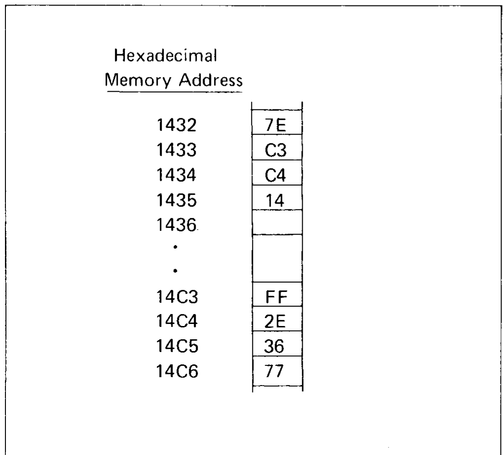
Assuming that registers H and L contain 14H and C3H respectively, the program operates as follows:
Byte 1432 specifies that the accumulator is to be loaded with the contents of byte 14C3.
Bytes 1433 through 1435 specify that execution is to continue with the instruction starting at byte 14C4.
Bytes 14C4 and 14C5 specify that the L register is to be loaded with the number 36H.
Byte 14C6 specifies that the contents of the accumulator are to be stored in byte 1436.
Now suppose that an error discovered in the program logic necessitates placing an extra instruction after byte 1432. Program code would have to change as follows:
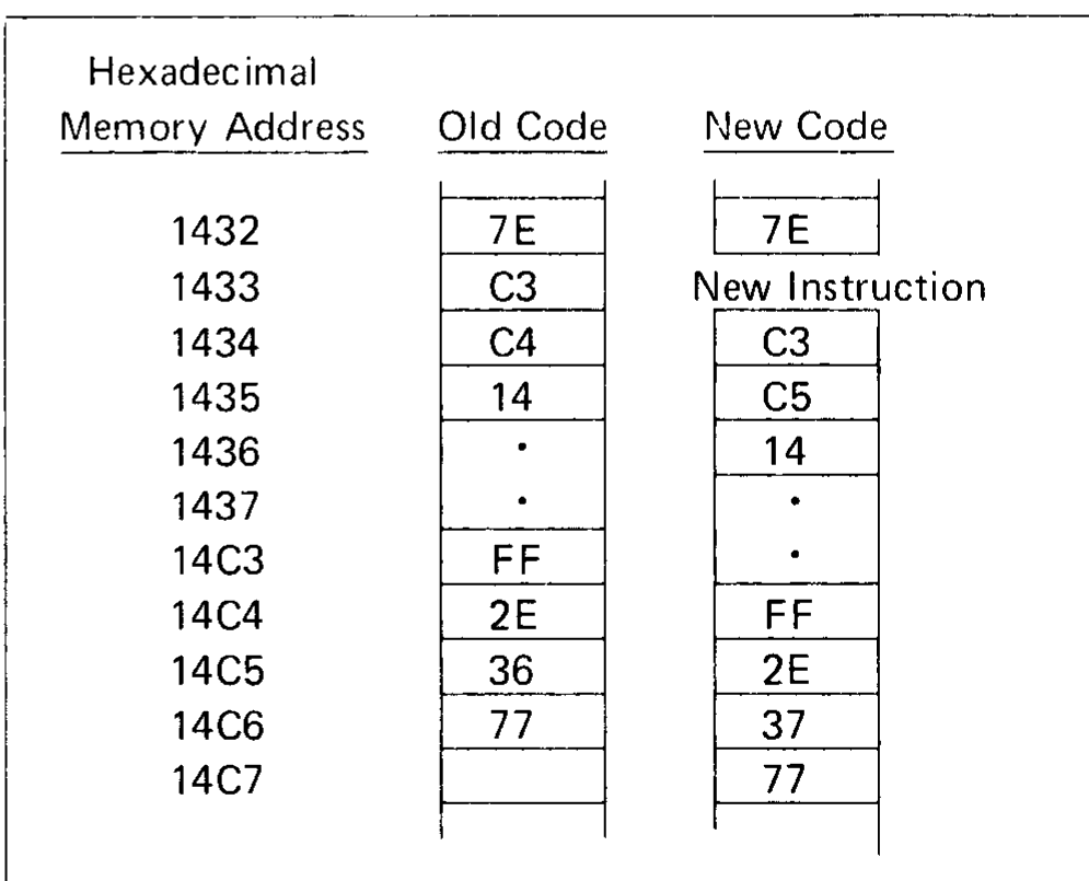
Most instructions have been moved and as a result many must be changed to reflect the new memory addresses of instructions or data. The potential for making mistakes is very high and is aggravated by the complete unreadability of the program.
Writing programs in assembly language is the first and most significant step towards economical programming; it provides a readable notation for instructions, and separates the programmer from a need to know or specify absolute memory addresses.
Assembly language programs are written as a sequence of instructions which are converted to executable hexadecimal code by a special program called an ASSEMBLER. Use of the 8080 assembler is described in its operator’s manual.
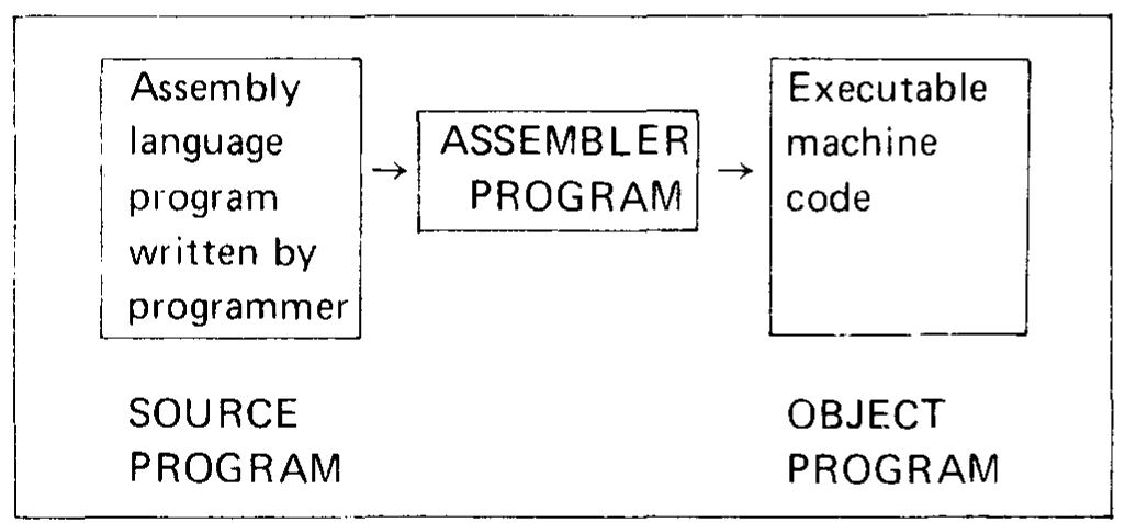
Figure 2-1. Assembler Program Converts Assembly Language Source Program to Object Program
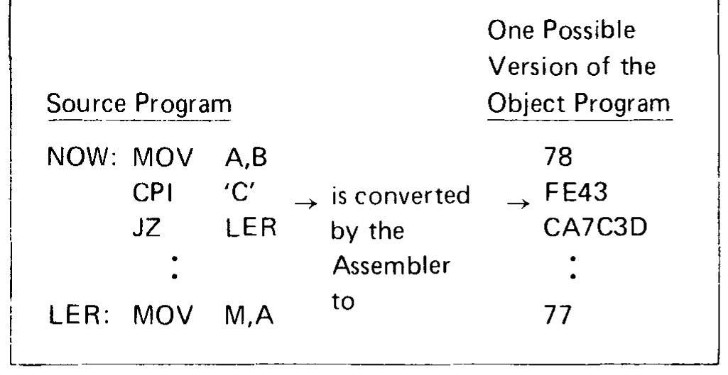
As illustrated in Figure 2-1, the assembly language program generated by a programmer is called a SOURCE PROGRAM. The assembler converts the SOURCE PROGRAM into an equivalent OBJECT PROGRAM, which consists of a sequence of binary codes that can be loaded into memory and executed.
For example:
Note
In this and subsequent examples, it is not necessary to understand the operations of the individual instructions. They are presented only to illustrate typical assembly language statements. Individual instructions are described later in this chapter.
Now if a new instruction must be added, only one change is required. Even the reader who is not yet familiar with assembly language will see how simple the addition is:
NOW:    MOV     A,B
        (New instruction inserted here)
        CPI     'C'
        JZ      LER
          .
          .
LER     MOV     M,A
The assembler takes care of the fact that a new instruction will shift the rest of the program in memory.
Statement Syntax
Assembly language instructions must adhere to a fixed set of rules as described in this section. An instruction has four separate and distinct parts or fields.
Field 1 is the LABEL field. It is a name used to reference the instruction’s address.
Field 2 is the CODE field. It specifies the operation that is to be performed.
Field 3 is the OPERAND field. It provides any address or data information needed by the CODE field.
Field 4 is the COMMENT field. It is present for the programmer’s convenience and is ignored by the assembler. The programmer uses comment fields to describe the operation and thus make the program more readable.
The assembler uses free fields; that is, any number of blanks may separate fields.
Before describing each field in detail, here are some general examples:
Label   Code    Operand
HERE:   MVI     C,0         ; Load the C register with 0
THERE:  DB      3AH         ; Create a one-byte data
                            ; constant
LOOP:   ADD     E           ; Add contents of E register
                            ; to the accumulator
        RLC                 ; Rotate the accumulator left
Note
These examples and the ones which follow are intended to illustrate how the various fields appear in complete assembly language statements. It is not necessary at this point to understand the operations which the statements perform.
Label Field
This is an optional field, which, if present, may be from 1 to 5 characters long. The first character of the label must be a letter of the alphabet or one of the special characters @ (at sign) or ? (question mark). A colon (:) must follow the last character. (The operation codes, pseudo-instruction names, and register names are specially defined within the assembler and may not be used as labels. Operation codes and pseudo-instructions are given later in this chapter and Appendix A.)
Here are some examples of valid label fields:
LABEL:
F14F:
@HERE:
?ZERO:
Here are some invalid label fields:
123:    begins with a decimal digit
LABEL   is not followed by a colon
ADD:    is an operation code
END:    is a pseudo-instruction
The following label has more than five characters; only the first five will be recognized:
INSTRUCTION: will be read as INSTR:
Since labels serve as instruction addresses, they cannot be duplicated. For example, the sequence:
HERE:   JMP     THERE
  .
  .
THERE:  MOV     C,D
  .
  .
THERE:  CALL    SUB
is ambiguous; the assembler cannot determine which address is to be referenced by the JMP instruction.
One instruction may have more than one label, however. The following sequence is valid:
LOOP1:                      ; First label
LOOP2:  MOV     C,D         ; Second label
  .
  .
        JMP     LOOP1
  .
  .
        JMP     LOOP2
Each JMP instruction will cause program control to be transferred to the same MOV instruction.
Code Field
This field contains a code which identifies the machine operation (add, subtract, jump, etc.) to be performed: hence the term operation code or op code. The instructions described later in this chapter are each identified by a mnemonic label which must appear in the code field. For example, since the “jump” instruction is identified by the letters “JMP,” these letters must appear in the code field to identify the instruction as “jump.”
There must be at least one space following the code field. Thus,
HERE: JMP THERE
is legal, but:
HERE JMPTHERE
is illegal.
Operand Field
This field contains information used in conjunction with the code field to define precisely the operation to be performed by the instruction. Depending upon the code field, the operand field may be absent or may consist of one item or two items separated by a comma.
There are four types of information [(a) through (d) below] that may be requested as items of an operand field, and the information may be specified in nine ways [(1) through (9) below], as summarized in the following table, and described in detail in the subsequent examples.
Information required |
Ways of specifying |
|---|---|
|
|
The nine ways of specifying information are as follows:
Hexadecimal data. Each hexadecimal number must be followed by a letter ‘H’ and must begin with a numeric digit (0-9).
Example:
Label   Code    Operand     Comment
HERE:   MVI     C,0BAH      ; Load register C with the
                            ; hexadecimal number BA
Decimal data. Each decimal number may optionally be followed by the letter ‘D,’ or may stand alone.
Example:
Label   Code    Operand     Comment
ABC:    MVI     E,105       ; Load register E with 105
Octal data. Each octal number must be followed by one of the letters ‘O’ or ‘Q.’
Example:
Label   Code    Operand     Comment
LABEL:  MVI     A,72Q       ; Load the accumulator with
                            ; the octal number 72
Binary data. Each binary number must be followed by the letter ‘B.’
Example:
Label   Code    Operand                 Comment
NOW:    MVI     10B,11110110B           ; Load register two
                                        ; (the D register) with
                                        ; 0F6H
JUMP:   JMP     0010111011111010B       ; Jump to
                                        ; memory
                                        ; address 2EFA
The current program counter. This is specified as the character ‘$’ and is equal to the address of the current instruction.
Example:
Label   Code    Operand
GO:     JMP     $+6
The instruction above causes program control to be transferred to the address 6 bytes beyond where the JMP instruction is loaded.
An ASCII constant. This is one or more ASCII characters enclosed in single quotes. Two successive single quotes must be used to represent one single quote within an ASCII constant. Appendix D contains a list of legal ASCII characters and their hexadecimal representations.
Example:
Label   Code    Operand     Comment
CHAR:   MVI     E,'*'       ; Load the E register with the
                            ; eight-bit ASCII representa-
                            ; tion of an asterisk
Labels that have been assigned a numeric value by the assembler. The following assignments are built into the assembler and are therefore always active:
B  assigned to 0  representing register B
C     "    "  1        "         "     C
D     "    "  2        "         "     D
E     "    "  3        "         "     E
H     "    "  4        "         "     H
L     "    "  5        "         "     L
M     "    "  6        "      a memory reference
A     "    "  7        "      register A
Example:
Suppose VALUE has been equated to the hexadecimal number 9FH. Then the following instructions all load the D register with 9FH:
Label   Code    Operand
A1:     MVI     D,VALUE
A2:     MVI     2,9FH
A3:     MVI     2,VALUE
Labels that appear in the label field of another instruction.
Example:
Label   Code    Operand     Comment
HERE:   JMP     THERE       ; Jump to instruction
                            ; at THERE
  .
  .
THERE:  MVI     D,9FH
Arithmetic and logical expressions involving data types (1) to (8) above connected by the arithmetic operators + (addition), - (unary minus and subtraction), * (multiplication), / (division), MOD (modulo), the logical operators NOT, AND, OR, XOR, SHR (shift right), SHL (shift left), and left and right parentheses.
All operators treat their arguments as 15-bit quantities, and generate 16-bit quantities as their result.
The operator + produces the arithmetic sum of its operands.
The operator - produces the arithmetic difference of its operands when used as subtraction, or the arithmetic negative of its operand when used as unary minus.
The operator * produces the arithmetic product of its operands.
The operator / produces the arithmetic integer quotient of its operands, discarding any remainder.
The operator MOD produces the integer remainder obtained by dividing the first operand by the second.
The operator NOT complements each bit of its operand.
The operator AND produces the bit-by-bit logical AND of its operands.
The operator OR produces the bit-by-bit logical OR of its operands.
The operator XOR produces the bit-by-bit logical EXCLUSIVE-OR of its operands.
The SHR and SHL operators are linear shifts which shift their first operands right or left, respectively, by the number of bit positions specified by their second operands. Zeros are shifted into the high-order or low-order bits, respectively, of their first operands.
The programmer must insure that the result generated by any operation fits the requirements of the operation being coded. For example, the second operand of an MVI instruction must be an 8-bit value. Therefore the instruction:
MVI H,NOT 0
is invalid, since NOT 0 produces the 16-bit hexadecimal number FFFF. However, the instruction:
MVI H,NOT 0 AND 0FFH
is valid, since the most significant 8 bits of the result are insured to be 0, and the result can therefore be represented in 8 bits.
Note
An instruction in parentheses is a legal expression of an optional field. Its value is the encoding of the instruction.
Examples:
                                    Arbitrary
Label   Code    Operand             Memory Address
HERE:   MVI     C,HERE SHR 8        2E1A
The above instruction loads the hexadecimal number 2EH (16-bit address of HERE shifted right 8 bits) into the C register.
Label   Code    Operand
NEXT:   MVI     D,34+40H/2
The above instruction will load the value 34+(64/2) = 34+32 = 66 into the D register.
Label   Code    Operand
INS:    DB      (ADD C)
The above instruction defines a byte of value 81H (the encoding of an ADD C instruction) at location INS.
Operators cause expressions to be evaluated in the following order:
Parenthesized expressions
*, /, MOD, SHL, SHR
+, - (unary and binary)
NOT
AND
OR, XOR
In the case of parenthesized expressions, the most deeply parenthesized expressions are evaluated first:
Example:
The instruction:
MVI D,(34+40H)/2
will load the value (34+64)/2 = 49 into the D register.
The operators MOD, SHL, SHR, NOT, AND, OR, and XOR must be separated from their operands by at least one blank. Thus the instruction:
MVI C,VALUE AND0FH
is invalid.
Using some or all of the above nine data specifications, the following four types of information may be requested:
A register (or code indicating memory reference) to serve as the source or destination in a data operation—methods 1, 2, 3, 4, 7, or 9 may be used to specify the register or memory reference, but the specifications must finally evaluate to one of the numbers 0-7 as follows:
Value
Register
0
B
1
C
2
D
3
E
4
H
5
L
6
Memory Reference
7
A (accumulator)
Example:
Label   Code    Operand
INS1:   MVI     REG4,2EH
INS2:   MVI     4H,2EH
INS3:   MVI     8/2,2EH
Assuming REG4 has been equated to 4, all the above instructions will load the value 2EH into register 4 (the H register).
A register pair to serve as the source or destination in a data operation. Register pairs are specified as follows:
Specification
Register Pair
B
Registers B and C
D
Registers D and E
H
Registers H and L
PSW
One byte indicating the state of the condition bits, and Register A (see Sections 4.9.1 and 4.9.2)
SP
The 16-bit stack pointer register
Note
The binary value representing each register pair varies from instruction to instruction. Therefore, the programmer should always specify a register pair by its alphabetic designation.
Example:
Label   Code    Operand     Comment
        PUSH    D           ; Push registers D and
                            ; E onto stack
        INX     SP          ; Increment 16-bit
                            ; number in the stack
                            ; pointer
Immediate data, to be used directly as a data item.
Example:
Label   Code    Operand     Comment
HERE:   MVI     H,DATA      ; Load the H register with
                            ; the value of DATA
Here are some examples of the form DATA could take:
ADDR AND 0FFH   (where ADDR is a 16-bit address)
127
'*'
VALUE           (where VALUE has been equated to a
                 number)
3EH=10/2 (2 AND 2)
Todo
The last DATA example,
3EH=10/2 (2 AND 2), is transcribed as it appears in the scan (scans/page-18.png), but it doesn’t look like a valid expression. It may be a misprint in the original.A 16-bit address, or the label of another instruction in memory.
Example:
Label   Code    Operand     Comment
HERE:   JMP     THERE       ; Jump to the instruction
                            ; at THERE
        JMP     2EADH       ; Jump to address 2EAD
Data Statements
This section describes ways in which data can be specified in and interpreted by a program. Any 8-bit byte contains one of the 256 possible combinations of zeros and ones. Any particular combination may be interpreted in various ways. For instance, the code 1FH may be interpreted as a machine instruction (Rotate Accumulator Right Through Carry), as a hexadecimal value 1FH=31D, or merely as the bit pattern 00011111.
Arithmetic instructions assume that the data bytes upon which they operate are in a special format called “two’s complement,” and the operations performed on these bytes are called “two’s complement arithmetic.”
Two’s Complement Representation
When a byte is interpreted as a signed two’s complement number, the low-order 7 bits supply the magnitude of the number, while the high-order bit is interpreted as the sign of the number (0 for positive numbers, 1 for negative).
The range of positive numbers that can be represented in signed two’s complement notation is, therefore, from 0 to 127:
   0 = 00000000B = 0H
   1 = 00000001B = 1H
     .
     .
126D = 01111110B = 7EH
127D = 01111111B = 7FH
To change the sign of a number represented in two’s complement, the following rules are applied:
Complement each bit of the number (producing the so-called one’s complement).
Add one to the result, ignoring any carry out of the high-order bit position.
- Example:
Produce the two’s complement representation of -10D. Following the rules above:
+10D = 00001010B
Complement each bit :  11110101B
Add one             :  11110110B
Therefore, the two’s complement representation of -10D is F6H. (Note that the sign bit is set, indicating a negative number).
- Example:
What is the value of 86H interpreted as a signed two’s complement number? The high-order bit is set, indicating that this is a negative number. To obtain its value, again complement each bit and add one.
86H = 10000110B
Complement each bit :  01111001B
Add one             :  01111010B
Thus, the value of 86H is -7AH = -122D.
The range of negative numbers that can be represented in signed two’s complement notation is from -1 to -128.
  -1 = 11111111B = FFH
  -2 = 11111110B = FEH
     .
     .
-127D = 10000001B = 81H
-128D = 10000000B = 80H
To perform the subtraction 1AH-0CH, the following operations are performed:
Take the two’s complement of 0CH=F4H
Add the result to the minuend:
     1AH = 00011010
+(-0CH) = F4H = 11110100
                --------
              1 00001110 = 0EH  the correct answer
When a byte is interpreted as an unsigned two’s complement number, its value is considered positive and in the range 0 to 25510:
   0 = 00000000B = 0H
   1 = 00000001B = 1H
     .
     .
127D = 01111111B = 7FH
128D = 10000000B = 80H
     .
     .
255D = 11111111B = FFH
Two’s complement arithmetic is still valid. When performing an addition operation, the Carry bit is set when the result is greater than 255D. When performing subtraction, the Carry bit is reset when the result is positive. If the Carry bit is set, the result is negative and present in its two’s complement form. Thus, the Carry bit when set indicates the occurrence of a “borrow.”
- Example:
Subtract 98D from 197D using unsigned two’s complement arithmetic.
   197D = 11000101 = C5H
   -98D = 10011110 = 9EH
          --------
carry  1  01100011 = 63H = 99D
out -->
Since the carry out of bit 7 = 1, indicating that the answer is correct and positive, the subtract operation will reset the Carry bit to 0.
- Example:
Subtract 15D from 12D using unsigned two’s complement arithmetic.
    12D = 00001100 = 0CH
   -15D = 11110001 = 0F1H
          --------
carry  0  11111101 = -3D
out -->
Since the carry out of bit 7 = 0, indicating that the answer is negative and in its two’s complement form, the subtract operation will set the Carry bit indicating that a “borrow” occurred.
Note
The 8080 instructions which perform the subtraction operation are SUB, SUI, SBB, SBI, CMP, and CMI. Although the same result will be obtained by addition of a complemented number or subtraction of an uncomplemented number, the resulting Carry bit will be different.
Todo
“CMI” in the note above is transcribed as printed. It is probably a misprint for CPI (chapter 1 lists SUB, SBB, SUI, SBI, CMP, and CPI).
- EXAMPLE:
If the result -3 is produced by performing an “ADD” operation on the numbers +12D and -15D, the Carry bit will be reset; if the same result is produced by performing a “SUB” operation on the numbers +12D and +15D, the Carry bit will be set. Both operations indicate that the result is negative; the programmer must be aware which operations set or reset the Carry bit.
"ADD" +12D and -15D                "SUB" +15D from +12D

   +12D  = 00001100                   +12D  = 00001100
+(-15D)  = 11110001                -(+15D)  = 11110001
         0 11111101 = -3D                   0 11111101 = -3D
         |                                  |
         causes carry to be reset           causes carry to be set
DB Define Byte(s) of Data
Format:
Label   Code    Operand
oplab:  DB      list
“list” is a list of either:
Arithmetic and logical expressions involving any of the arithmetic and logical operators, which evaluate to eight-bit data quantities
Strings of ASCII characters enclosed in quotes
Description: The eight-bit value of each expression, or the eight-bit ASCII representation of each character is stored in the next available byte of memory starting with the byte addressed by “oplab.” (The most significant bit of each ASCII character is always = 0).
Example:
Instruction                     Assembled Data (hex)
HERE:   DB  0A3H                A3
WORD1:  DB  5*2,2FH-0AH         0A25
WORD2:  DB  5ABCH SHR 8         5A
STR:    DB  'STRINGSpl'         535452494E472031
MINUS:  DB  -03H                FD
Todo
The STR example (scans/page-20.png) is printed as 'STRINGSpl' with
assembled data 535452494E472031. That data spells “STRING 1”, so the
string was probably meant to be 'STRING 1' and the “Sp” stands for a
space. Decide whether to keep the literal text or add an editorial note.
Note
In the first example above, the hexadecimal value A3 must be written as 0A3 since hexadecimal numbers must start with a decimal digit.
DW Define Word (Two Bytes) of Data
Format:
Label   Code    Operand
oplab:  DW      list
“list” is a list of expressions which evaluate to 16 bit data quantities.
Description: The least significant 8 bits of the expression are stored in the lower address memory byte (oplab), and the most significant 8 bits are stored in the next higher addressed byte (oplab +1). This reverse order of the high and low address bytes is normally the case when storing addresses in memory. This statement is usually used to create address constants for the transfer-of-control instructions; thus LIST is usually a list of one or more statement labels appearing elsewhere in the program.
Examples:
Assume COMP address memory location 3B1CH and FILL addresses memory location 3EB4H.
                                    Assembled
Instruction                         Data (hex)
ADD1:   DW  COMP                    1C3B
ADD2:   DW  FILL                    B43E
ADD3:   DW  3C01H, 3CAEH            013CAE3C
Note that in each case, the data are stored with the least significant 8 bits first.
DS Define Storage (Bytes)
Format:
Label   Code    Operand
oplab:  DS      exp
“exp” is a single arithmetic or logical expression.
Description: The value of EXP specifies the number of memory bytes to be reversed for data storage. No data values are assembled into these bytes: in particular the programmer should not assume that they will be zero, or any other value. The next instruction will be assembled at memory location oplab+EXP (oplab+10 or oplab+16 in the example below).
Examples:
HERE:   DS      10      ; Reserve the next 10 bytes
        DS      10H     ; Reserve the next 16 bytes
Carry Bit Instructions
This section describes the instructions which operate directly upon the Carry bit. Instructions in this class occupy one byte as follows:
+---+---+---+---+---+---+---+---+
| 0 | 0 | 1 | 1 | X | 1 | 1 | 1 |
+---+---+---+---+---+---+---+---+
X = 0 for STC, 1 for CMC
The general assembly language format is:
Label   Code    Operand
LABEL:  OP
  |      |       |
  |      |       +-- not used
  |      +---------- STC or CMC
  +----------------- Optional instruction label
CMC Complement Carry
Format:
Label   Code    Operand
oplab:  CMC     --
+---+---+---+---+---+---+---+---+
| 0 | 0 | 1 | 1 | 1 | 1 | 1 | 1 |
+---+---+---+---+---+---+---+---+
Description: If the Carry bit = 0, it is set to 1. If the Carry bit = 1, it is reset to 0.
Condition bits affected: Carry
STC Set Carry
Format:
Label   Code    Operand
oplab:  STC     --
+---+---+---+---+---+---+---+---+
| 0 | 0 | 1 | 1 | 0 | 1 | 1 | 1 |
+---+---+---+---+---+---+---+---+
Description: The Carry bit is set to one.
Condition bits affected: Carry
Single Register Instructions
This section describes instructions which operate on a single register or memory location. If a memory reference is specified, the memory byte addressed by the H and L registers is operated upon. The H register holds the most significant 8 bits of the address while the L register holds the least significant 8 bits of the address.
INR Increment Register or Memory
Format:
Label   Code    Operand
oplab:  INR     reg
                 |
                 +-- B,C,D,E,H,L,M or A
+---+---+-----------+---+---+---+
| 0 | 0 |    reg    | 1 | 0 | 0 |
+---+---+-----------+---+---+---+
reg = 000 for register B
      001 for register C
      010 for register D
      011 for register E
      100 for register H
      101 for register L
      110 for memory ref. M
      111 for register A
Description: The specified register or memory byte is incremented by one.
Condition bits affected: Zero, Sign, Parity, Auxiliary Carry
Example:
If register C contains 99H, the instruction:
INR C
will cause register C to contain 9AH
DCR Decrement Register or Memory
Format:
Label   Code    Operand
oplab:  DCR     reg
                 |
                 +-- B,C,D,E,H,L,M or A
+---+---+-----------+---+---+---+
| 0 | 0 |    reg    | 1 | 0 | 1 |
+---+---+-----------+---+---+---+
reg = 000 for register B
      001 for register C
      010 for register D
      011 for register E
      100 for register H
      101 for register L
      110 for memory ref. M
      111 for register A
Description: The specified register or memory byte is decremented by one.
Condition bits affected: Zero, Sign, Parity, Auxiliary Carry
Example:
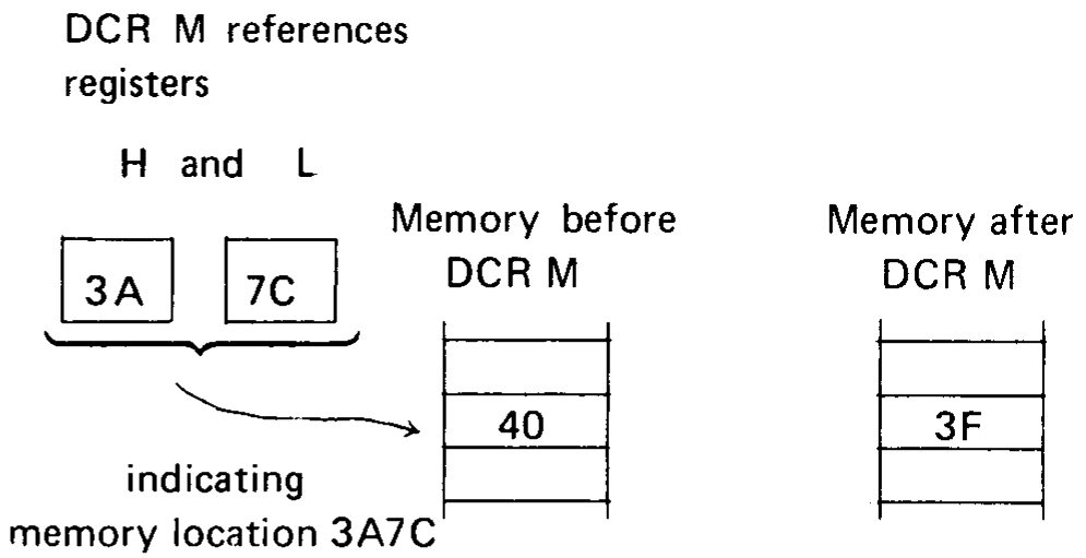
If the H register contains 3AH, the L register contains 7CH, and memory location 3A7CH contains 40H, the instruction:
DCR M
will cause memory location 3A7CH to contain 3FH. To illustrate:
CMA Complement Accumulator
Format:
Label   Code    Operand
oplab:  CMA     --
+---+---+---+---+---+---+---+---+
| 0 | 0 | 1 | 0 | 1 | 1 | 1 | 1 |
+---+---+---+---+---+---+---+---+
Description: Each bit of the contents of the accumulator is complemented (producing the one’s complement).
Condition bits affected: None
Example:
If the accumulator contains 51H, the instruction CMA will cause the accumulator to contain 0AEH.
Accumulator = 01010001 = 51H
Accumulator = 10101110 = AEH
DAA Decimal Adjust Accumulator
Format:
Label   Code    Operand
oplab:  DAA     --
+---+---+---+---+---+---+---+---+
| 0 | 0 | 1 | 0 | 0 | 1 | 1 | 1 |
+---+---+---+---+---+---+---+---+
Description: The eight-bit hexadecimal number in the accumulator is adjusted to form two four-bit binary-coded-decimal digits by the following two step process:
If the least significant four bits of the accumulator represents a number greater than 9, or if the Auxiliary Carry bit is equal to one, the accumulator is incremented by six. Otherwise, no incrementing occurs.
If the most significant four bits of the accumulator now represent a number greater than 9, or if the normal carry bit is equal to one, the most significant four bits of the accumulator are incremented by six. Otherwise, no incrementing occurs.
If a carry out of the least significant four bits occurs during Step (1), the Auxiliary Carry bit is set; otherwise it is reset. Likewise, if a carry out of the most significant four bits occurs during Step (2), the normal Carry bit is set; otherwise, it is unaffected:
Note
This instruction is used when adding decimal numbers. It is the only instruction whose operation is affected by the Auxiliary Carry bit.
Condition bits affected: Zero, Sign, Parity, Carry, Auxiliary Carry
Example:
Suppose the accumulator contains 9BH, and both carry bits = 0. The DAA instruction will operate as follows:
Since bits 0-3 are greater than 9, add 6 to the accumulator. This addition will generate a carry out of the lower four bits, setting the Auxiliary Carry bit.
Bit No.         7 6 5 4   3 2 1 0
Accumulator =   1 0 0 1   1 0 1 1 = 9BH
         +6 =             0 1 1 0
                -----------------
                1 0 1 0   0 0 0 1 = A1H
                         |
                         +--> Auxiliary Carry = 1
Since bits 4-7 now are greater than 9, add 6 to these bits. This addition will generate a carry out of the upper four bits, setting the Carry bit.
Bit No.         7 6 5 4 3 2 1 0
Accumulator =   1 0 1 0 0 0 0 1 = A1H
         +6 =   0 1 1 0
              -----------------
              1 0 0 0 0 0 0 0 1
              |
              +--> Carry = 1
Thus, the accumulator will now contain 1, and both Carry bits will be = 1.
For an example of decimal addition using the DAA instruction, see Chapter 4.
NOP Instructions
The NOP instruction occupies one byte.
Format:
Label   Code    Operand
oplab   NOP     --
+---+---+---+---+---+---+---+---+
| 0 | 0 | 0 | 0 | 0 | 0 | 0 | 0 |
+---+---+---+---+---+---+---+---+
Description: No operation occurs. Execution proceeds with the next sequential instruction.
Condition bits affected: None
Data Transfer Instructions
This section describes instructions which transfer data between registers or between memory and registers.
Instructions in this class occupy one byte as follows:
For the MOV instruction:
+---+---+-----------+-----------+
| 0 | 1 |    dst    |    src    |
+---+---+-----------+-----------+
dst, src = 000 for register B
           001 for register C
           010 for register D
           011 for register E
           100 for register H
           101 for register L
           110 for memory reference M
           111 for register A
Note
dst and src cannot both = 110B
For the remaining instructions:
+---+---+---+---+---+---+---+---+
| 0 | 0 | 0 | X | X | 0 | 1 | 0 |
+---+---+---+---+---+---+---+---+
bit 4:  0 for register pair B       bit 3:  0 for STAX
        1 for register pair D               1 for LDAX
When a memory reference is specified in the MOV instruction, the addressed location is specified by the H and L registers. The L register holds the least significant 8 bits of the address; the H register holds the most significant 8 bits.
The general assembly language format is:
Label   Code    Operand
oplab:  MOV     dst,src
  |              |   |
  |              +---+-- A,B,C,D,E,H,L, or M
  |                      (dst and src not both = M)
  +--------------------- Optional instruction label

- or -

Label   Code    Operand
oplab:  OP      rp
  |      |       |
  |      |       +-- B or D
  |      +---------- STAX or LDAX
  +----------------- Optional instruction label
MOV Instruction
Format:
Label   Code    Operand
oplab:  MOV     dst,src
+---+---+-----------+-----------+
| 0 | 1 |    dst    |    src    |
+---+---+-----------+-----------+
Description: One byte of data is moved from the register specified by src (the source register) to the register specified by dst (the destination register). The data replaces the contents of the destination register; the source remains unchanged.
Condition bits affected: None
Example 1:
Label   Code    Operand     Comment
        MOV     A,E         ; Move contents of the E
                            ; register to the A register
        MOV     D,D         ; Move contents of the
                            ; D register to the D
                            ; register, i.e., this is a
                            ; null operation
Note
Any of the null operation instructions MOV X,X can also be specified as NOP (no-operation).
Example 2:
Assuming that the H register contains 2BH and the L register contains E9H, the instruction:
MOV M,A
will store the contents of the accumulator at memory location 2BE9H.
STAX Store Accumulator
Format:
Label   Code    Operand
oplab:  STAX    rp
+---+---+---+---+---+---+---+---+
| 0 | 0 | 0 | X | 0 | 0 | 1 | 0 |
+---+---+---+---+---+---+---+---+
Description: The contents of the accumulator are stored in the memory location addressed by registers B and C, or by registers D and E.
Condition bits affected: None
Example:
If register B contains 3FH and register C contains 16H, the instruction:
STAX B
will store the contents of the accumulator at memory location 3F16H.
LDAX Load Accumulator
Format:
Label   Code    Operand
oplab:  LDAX    rp
+---+---+---+---+---+---+---+---+
| 0 | 0 | 0 | X | 1 | 0 | 1 | 0 |
+---+---+---+---+---+---+---+---+
Description: The contents of the memory location addressed by registers B and C, or by registers D and E, replace the contents of the accumulator.
Condition bits affected: None
Example:
If register D contains 93H and register E contains 8BH, the instruction:
LDAX D
will load the accumulator from memory location 938BH.
Register or Memory to Accumulator Instructions
This section describes the instructions which operate on the accumulator using a byte fetched from another register or memory. Instructions in this class occupy one byte as follows:
+---+---+-----------+-----------+
| 1 | 0 |     op    |    reg    |
+---+---+-----------+-----------+
op  = 000 for ADD           reg = 000 for register B
      001 for ADC                 001 for register C
      010 for SUB                 010 for register D
      011 for SBB                 011 for register E
      100 for ANA                 100 for register H
      101 for XRA                 101 for register L
      110 for ORA                 110 for memory reference M
      111 for CMP                 111 for register A
Instructions in this class operate on the accumulator using the byte in the register specified by REG. If a memory reference is specified, the instructions use the byte in the memory location addressed by registers H and L. The H register holds the most significant 8 bits of the address, while the L register holds the least significant 8 bits of the address. The specified byte will remain unchanged by any of the instructions in this class; the result will replace the contents of the accumulator.
The general assembly language instruction format is:
Label   Code    Operand
oplab:  op      reg
  |      |       |
  |      |       +-- A,B,C,D,E,H,L, or M
  |      +---------- ADD, ADC, SUB, SBB, ANA, XRA, ORA
  |                  or CMP
  +----------------- Optional instruction label
ADD ADD Register or Memory To Accumulator
Format:
Label   Code    Operand
oplab:  ADD     reg
+---+---+---+---+---+-----------+
| 1 | 0 | 0 | 0 | 0 |    reg    |
+---+---+---+---+---+-----------+
Description: The specified byte is added to the contents of the accumulator using two’s complement arithmetic.
Condition bits affected: Carry, Sign, Zero, Parity, Auxiliary Carry
Example 1:
Assume that the D register contains 2EH and the accumulator contains 6CH. Then the instruction:
ADD D
will perform the addition as follows:
2EH = 00101110
6CH = 01101100
      --------
9AH = 10011010
The Zero and Carry bits are reset; the Parity and Sign bits are set. Since there is a carry out of bit A3, the Auxiliary Carry bit is set. The accumulator now contains 9AH.
Example 2:
The instruction:
ADD A
will double the accumulator.
ADC ADD Register or Memory To Accumulator With Carry
Format:
Label   Code    Operand
oplab:  ADC     reg
+---+---+---+---+---+-----------+
| 1 | 0 | 0 | 0 | 1 |    reg    |
+---+---+---+---+---+-----------+
Description: The specified byte plus the content of the Carry bit is added to the contents of the accumulator.
Condition bits affected: Carry, Sign, Zero, Parity, Auxiliary Carry
Example:
Assume that register C contains 3DH, the accumulator contains 42H, and the Carry bit = 0. The instruction:
ADC C
will perform the addition as follows:
   3DH = 00111101
   42H = 01000010
 CARRY =        0
           --------
RESULT = 01111111 = 7FH
The results can be summarized as follows:
Accumulator = 7FH
Carry       = 0
Sign        = 0
Zero        = 0
Parity      = 0
Aux. Carry  = 0
If the Carry bit had been one at the beginning of the example, the following would have occurred:
   3DH = 00111101
   42H = 01000010
 CARRY =        1
           --------
RESULT = 10000000 = 80H

Accumulator = 80H
Carry       = 0
Sign        = 1
Zero        = 0
Parity      = 0
Aux. Carry  = 1
SUB Subtract Register or Memory From Accumulator
Format:
Label   Code    Operand
oplab:  SUB     reg
+---+---+---+---+---+-----------+
| 1 | 0 | 0 | 1 | 0 |    reg    |
+---+---+---+---+---+-----------+
Description: The specified byte is subtracted from the accumulator using two’s complement arithmetic.
If there is no carry out of the high-order bit position, indicating that a borrow occurred, the Carry bit is set; otherwise it is reset. (Note that this differs from an add operation, which resets the carry if no overflow occurs).
Condition bits affected: Carry, Sign, Zero, Parity, Auxiliary Carry
Example:
Assume that the accumulator contains 3EH. Then the instruction:
SUB A
will subtract the accumulator from itself producing a result of zero as follows:
    3EH =   00111110
+(-3EH) =   11000001    negate and add one
          +        1    to produce two's
            --------    complement
carry --> 1 00000000    Result = 0
Since there was a carry out of the high-order bit position, and this is a subtraction operation, the Carry bit will be reset.
Since there was a carry out of bit A3, the Auxiliary Carry bit will be set.
The Parity and Zero bits will also be set, and the Sign bit will be reset.
Thus the SUB A instruction can be used to reset the Carry bit (and zero the accumulator).
SBB Subtract Register or Memory From Accumulator With Borrow
Format:
Label   Code    Operand
oplab:  SBB     reg
+---+---+---+---+---+-----------+
| 1 | 0 | 0 | 1 | 1 |    reg    |
+---+---+---+---+---+-----------+
Description: The Carry bit is internally added to the contents of the specified byte. This value is then subtracted from the accumulator using two’s complement arithmetic.
This instruction is most useful when performing subtractions. It adjusts the result of subtracting two bytes when a previous subtraction has produced a negative result (a borrow). For an example of this, see the section on Multibyte Addition and Subtraction in Chapter 4.
Condition bits affected: Carry, Sign, Zero, Parity, Auxiliary Carry (see last section for details).
Example:
Assume that register L contains 2, the accumulator contains 4, and the Carry bit = 1. Then the instruction SBB L will act as follows:
02H + Carry = 03H
Two's Complement of 03H = 11111101
Adding this to the accumulator produces:
Accumulator = 04H =   00000100
                      11111101
                    ----------
                    1 00000001 = 01H = Result
                    |
                    +--> carry out = 1 causing the Carry bit to be reset
The final result stored in the accumulator is one, causing the Zero bit to be reset. The Carry bit is reset since this is a subtract operation and there was a carry out of the high-order bit position. The Auxiliary Carry bit is set since there was a carry out of bit A3. The Parity and the Sign bits are reset.
ANA Logical and Register or Memory With Accumulator
Format:
Label   Code    Operand
oplab:  ANA     reg
+---+---+---+---+---+-----------+
| 1 | 0 | 1 | 0 | 0 |    reg    |
+---+---+---+---+---+-----------+
Description: The specified byte is logically ANDed bit by bit with the contents of the accumulator. The Carry bit is reset to zero.
The logical AND function of two bits is 1 if and only if both the bits equal 1.
Condition bits affected: Carry, Zero, Sign, Parity
Example:
Since any bit ANDed with a zero produces a zero and any bit ANDed with a one remains unchanged, the AND function is often used to zero groups of bits.
Assuming that the accumulator contains 0FCH and the C register contains 0FH, the instruction:
ANA C
will act as follows:
Accumulator = 11111100 = 0FCH
C Register  = 00001111 = 0FH
              --------
Result in
Accumulator = 00001100 = 0CH
This particular example guarantees that the high-order four bits of the accumulator are zero, and the low-order four bits are unchanged.
XRA Logical Exclusive-Or Register or Memory With Accumulator (Zero Accumulator)
Format:
Label   Code    Operand
oplab:  XRA     reg
+---+---+---+---+---+-----------+
| 1 | 0 | 1 | 0 | 1 |    reg    |
+---+---+---+---+---+-----------+
Description: The specified byte is EXCLUSIVE-ORed bit by bit with the contents of the accumulator. The Carry bit is reset to zero.
The EXCLUSIVE-OR function of two bits equals 1 if and only if the values of the bits are different.
Condition bits affected: Carry, Zero, Sign, Parity, Auxiliary Carry
Example 1:
Since any bit EXCLUSIVE-ORed with itself produces zero, the EXCLUSIVE-OR can be used to zero the accumulator.
Label   Code    Operand
        XRA     A
        MOV     B,A
        MOV     C,A
These instructions zero the A, B, and C registers.
Example 2:
Any bit EXCLUSIVE-ORed with a one is complemented (0 XOR 1 = 1, 1 XOR 1 = 0).
Therefore if the accumulator contains all ones (0FFH), the instruction:
XRA B
will produce the one’s complement of the B register in the accumulator.
Example 3:
Testing for change of status.
Many times a byte is used to hold the status of several (up to eight) conditions within a program, each bit signifying whether a condition is true or false, enabled or disabled, etc.
The EXCLUSIVE-OR function provides a quick means of determining which bits of a word have changed from one time to another.
Label   Code    Operand
LA:     MOV     A,M         ; STAT2 to accumulator
        INX     H           ; Address next location
LB:     MOV     B,M         ; STAT1 to B register
CHNG:   XRA     B           ; EXCLUSIVE-OR
                            ; STAT1 and STAT2
STAT:   ANA     B           ; AND result with STAT1
  .
  .
STAT2:  DS      1
STAT1:  DS      1
Assume that logic elsewhere in the program has read the status of eight conditions and stored the corresponding string of eight zeros and ones at STAT1 and at some later time has read the same conditions and stored the new status at STAT2. Also assume that the H and L registers have been initialized to address location STAT2. The EXCLUSIVE-OR at CHNG produces a one bit in the accumulator wherever a condition has changed between STAT1 and STAT2.
For example:
Bit Number          76543210
STAT1 = 5CH =       01011100
STAT2 = 78H =       01111000
                    --------
EXCLUSIVE-OR:       00100100
This shows that the conditions associated with bits 2 and 5 have changed between STAT1 and STAT2. Knowing this, the program can tell whether these bits were set or reset by ANDing the result with STAT1.
Result = 00100100
STAT1  = 01011100
         --------
AND    = 00000100
Since bit 2 is now one, it was set between STAT1 and STAT2; since bit 5 is zero it is reset.
ORA Logical or Register or Memory With Accumulator
Format:
Label   Code    Operand
oplab:  ORA     reg
+---+---+---+---+---+-----------+
| 1 | 0 | 1 | 1 | 0 |    reg    |
+---+---+---+---+---+-----------+
Description: The specified byte is logically ORed bit by bit with the contents of the accumulator. The carry bit is reset to zero.
The logical OR function of two bits equals zero if and only if both the bits equal zero.
Condition bits affected: Carry, zero, sign, parity
Example:
Since any bit ORed with a one produces a one, and any bit ORed with a zero remains unchanged, the OR function is often used to set groups of bits to one.
Assuming that register C contains 0FH and the accumulator contains 33H, the instruction:
ORA C
acts as follows:
Accumulator = 00110011 = 33H
C Register  = 00001111 = 0FH
              --------
Result = Accumulator = 00111111 = 3FH
This particular example guarantees that the low-order four bits of the accumulator are one, and the high-order four bits are unchanged.
CMP Compare Register or Memory With Accumulator
Format:
Label   Code    Operand
oplab:  CMP     reg
+---+---+---+---+---+-----------+
| 1 | 0 | 1 | 1 | 1 |    reg    |
+---+---+---+---+---+-----------+
Description: The specified byte is compared to the contents of the accumulator. The comparison is performed by internally subtracting the contents of REG from the accumulator (leaving both unchanged) and setting the condition bits according to the result. In particular, the Zero bit is set if the quantities are equal, and reset if they are unequal. Since a subtract operation is performed, the Carry bit will be set if there is no carry out of bit 7, indicating that the contents of REG are greater than the contents of the accumulator, and reset otherwise.
Note
If the two quantities to be compared differ in sign, the sense of the Carry bit is reversed.
Condition bits affected: Carry, Zero, Sign, Parity, Auxiliary Carry
Example 1:
Assume that the accumulator contains the number 0AH and the E register contains the number 05H. Then the instruction CMP E performs the following internal subtractions:
Accumulator     = 0AH =   00001010
+ (-E Register) = -5H =   11111011
                        ----------
                        1 00000101 = result
                        |
                        +--> carry = 1, causing the Carry bit to be reset
The accumulator still contains 0AH and the E register still contains 05H; however, the Carry bit is reset and the zero bit reset, indicating E less than A.
Example 2:
If the accumulator had contained the number 2H, the internal subtraction would have produced the following:
Accumulator     = 02H =   00000010
+ (-E Register) = -5H =   11111011
                        ----------
                        0 11111101 = result
                        |
                        +--> carry = 0, Carry bit = 1
The Zero bit would be reset and the Carry bit set, indicating E greater than A.
Example 3:
Assume that the accumulator contains -1BH. The internal subtraction now produces the following:
Accumulator     = -1BH =   11100101
+ (-E Register) =  -5H =   11111011
                         ----------
                         1 11100000
                         |
                         +--> carry = 1, causing carry to be reset
Since the two numbers to be compared differed in sign, the resetting of the Carry bit now indicates E greater than A.
Rotate Accumulator Instructions
This section describes the instructions which rotate the contents of the accumulator. No memory locations or other registers are referenced.
Instructions in this class occupy one byte as follows:
+---+---+---+---+---+---+---+---+
| 0 | 0 | 0 | X | X | 1 | 1 | 1 |
+---+---+---+---+---+---+---+---+
XX = 00 for RLC
     01 for RRC
     10 for RAL
     11 for RAR
The general assembly language instruction format is:
Label   Code    Operand
label:  op
  |      |       |
  |      |       +-- not used
  |      +---------- RLC, RRC, RAL, or RAR
  +----------------- Optional instruction label
RLC Rotate Accumulator Left
Format:
Label   Code    Operand
oplab:  RLC     --
+---+---+---+---+---+---+---+---+
| 0 | 0 | 0 | 0 | 0 | 1 | 1 | 1 |
+---+---+---+---+---+---+---+---+
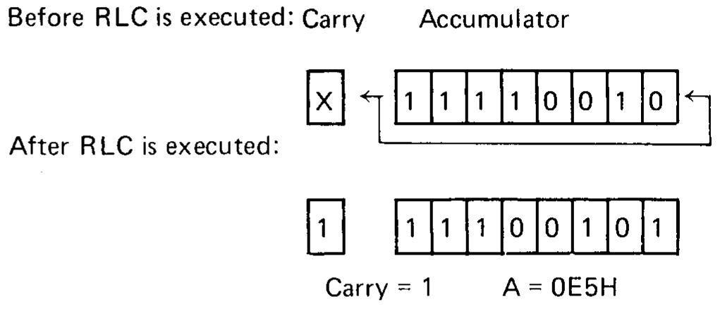
Description: The Carry bit is set equal to the high-order bit of the accumulator. The contents of the accumulator are rotated one bit position to the left, with the high-order bit being transferred to the low-order bit position of the accumulator.
Condition bits affected: Carry
Example:
Assume that the accumulator contains 0F2H. Then the instruction:
RLC
acts as follows:
RRC Rotate Accumulator Right
Format:
Label   Code    Operand
oplab:  RRC     --
+---+---+---+---+---+---+---+---+
| 0 | 0 | 0 | 0 | 1 | 1 | 1 | 1 |
+---+---+---+---+---+---+---+---+
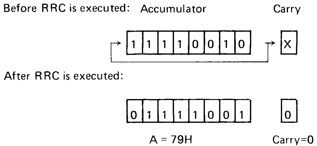
Description: The carry bit is set equal to the low-order bit of the accumulator. The contents of the accumulator are rotated one bit position to the right, with the low-order bit being transferred to the high-order bit position of the accumulator.
Condition bits affected: Carry
Example:
Assume that the accumulator contains 0F2H. Then the instruction:
RRC
acts as follows:
RAL Rotate Accumulator Left Through Carry
Format:
Label   Code    Operand
oplab:  RAL     --
+---+---+---+---+---+---+---+---+
| 0 | 0 | 0 | 1 | 0 | 1 | 1 | 1 |
+---+---+---+---+---+---+---+---+
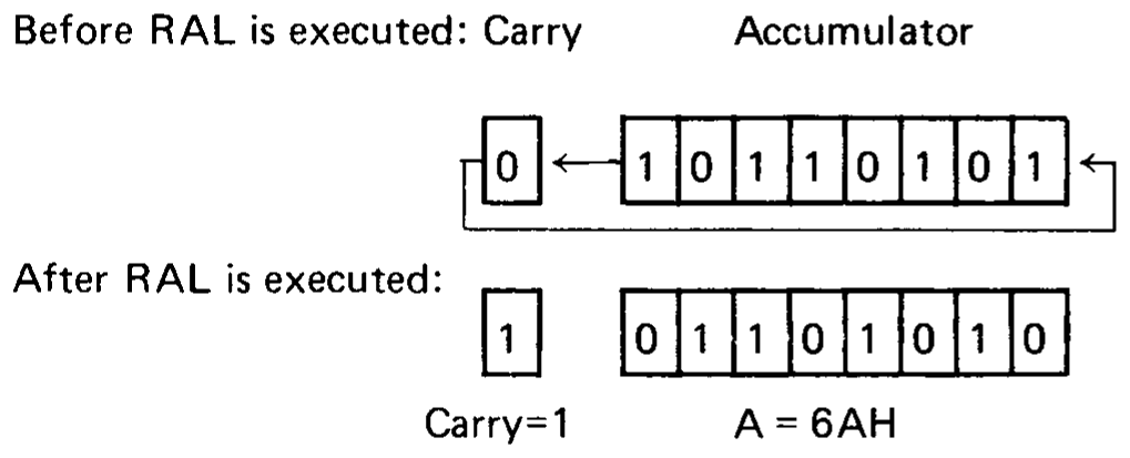
Description: The contents of the accumulator are rotated one bit position to the left.
The high-order bit of the accumulator replaces the Carry bit, while the Carry bit replaces the high-order bit of the accumulator.
Condition bits affected: Carry
Example:
Assume that the accumulator contains 0B5H. Then the instruction:
RAL
acts as follows:
RAR Rotate Accumulator Right Through Carry
Format:
Label   Code    Operand
oplab:  RAR     --
+---+---+---+---+---+---+---+---+
| 0 | 0 | 0 | 1 | 1 | 1 | 1 | 1 |
+---+---+---+---+---+---+---+---+
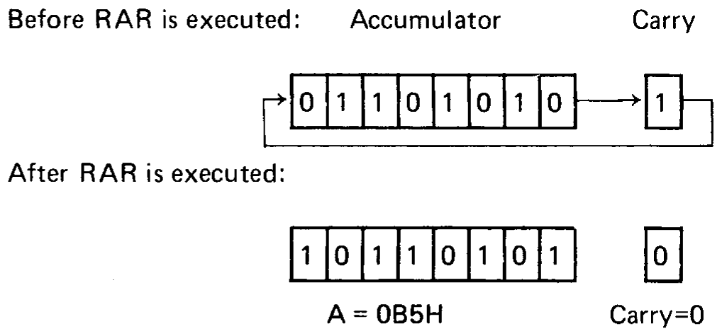
Description: The contents of the accumulator are rotated one bit position to the right.
The low-order bit of the accumulator replaces the carry bit, while the carry bit replaces the high-order bit of the accumulator.
Condition bits affected: Carry
Example:
Assume that the accumulator contains 6AH. Then the instruction:
RAR
acts as follows:
Register Pair Instructions
This section describes instructions which operate on pairs of registers.
PUSH Push Data Onto Stack
Format:
Label   Code    Operand
oplab:  PUSH    rp
                 |
                 +-- B,D,H, or PSW
+---+---+-------+---+---+---+---+
| 1 | 1 |   rp  | 0 | 1 | 0 | 1 |
+---+---+-------+---+---+---+---+
rp = 00 for registers B and C
     01 for registers D and E
     10 for registers H and L
     11 for flags and register A
Description: The contents of the specified register pair are saved in two bytes of memory indicated by the stack pointer SP.
The contents of the first register are saved at the memory address one less than the address indicated by the stack pointer; the contents of the second register are saved at the address two less than the address indicated by the stack pointer. If register pair PSW is specified, the first byte of information saved holds the contents of the A register; the second byte holds the settings of the five condition bits, i.e., Carry, Zero, Sign, Parity, and Auxiliary Carry. The format of this byte is:
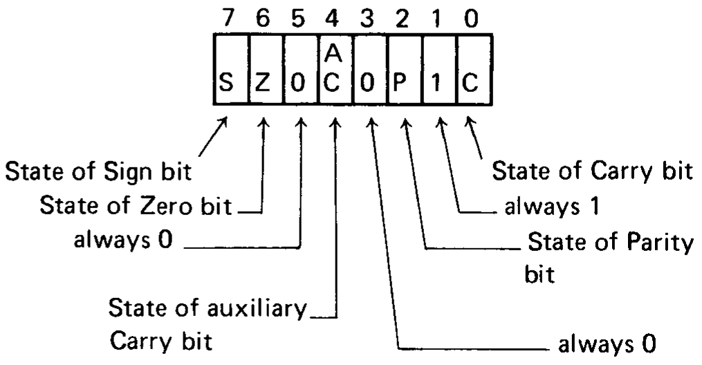
In any case, after the data has been saved, the stack pointer is decremented by two.
Condition bits affected: None
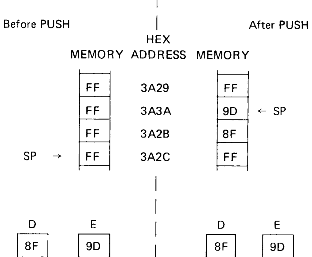
Example 1:
Assume that register D contains 8FH, register E contains 9DH, and the stack pointer contains 3A2CH. Then the instruction:
PUSH D
stores the D register at memory address 3A2BH, stores the E register at memory address 3A2AH, and then decrements the stack pointer by two, leaving the stack pointer equal to 3A2AH.
Example 2:
Assume that the accumulator contains 1FH, the stack pointer contains 502AH, the Carry, Zero and Parity bits all equal 1, and the Sign and Auxiliary Carry bits all equal 0. Then the instruction:
PUSH PSW
stores the accumulator (1FH) at location 5029H, stores the value 47H, corresponding to the flag settings, at location 5028H, and decrements the stack pointer to the value 5028H.
POP Pop Data Off Stack
Format:
Label   Code    Operand
oplab:  POP     rp
                 |
                 +-- B,D,H, or PSW
+---+---+-------+---+---+---+---+
| 1 | 1 |   rp  | 0 | 0 | 0 | 1 |
+---+---+-------+---+---+---+---+
rp = 00 for registers B and C
     01 for registers D and E
     10 for registers H and L
     11 for flags and register A
Description: The contents of the specified register pair are restored from two bytes of memory indicated by the stack pointer SP. The byte of data at the memory address indicated by the stack pointer is loaded into the second register of the register pair; the byte of data at the address one greater than the address indicated by the stack pointer is loaded into the first register of the pair. If register pair PSW is specified, the byte of data indicated by the contents of the stack pointer plus one is used to restore the values of the five condition bits (Carry, Zero, Sign, Parity, and Auxiliary Carry) using the format described in the last section.
In any case, after the data has been restored, the stack pointer is incremented by two.
Condition bits affected: If register pair PSW is specified, Carry, Sign, Zero, Parity, and Auxiliary Carry may be changed. Otherwise, none are affected.
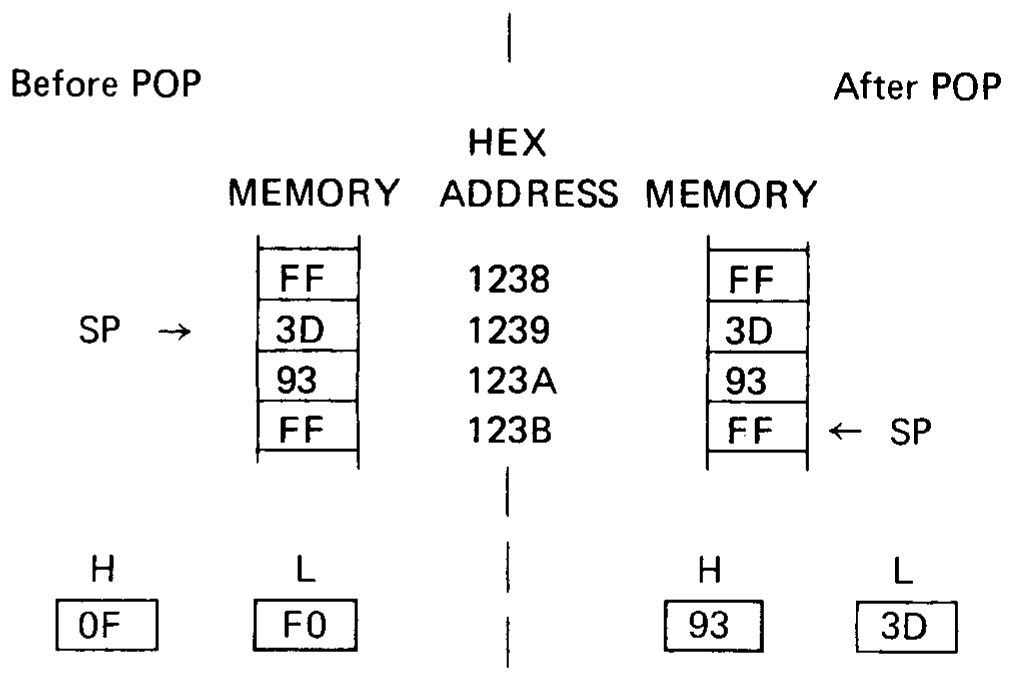
Example 1:
Assume that memory locations 1239H and 123AH contain 3DH and 93H, respectively, and that the stack pointer contains 1239H. Then the instruction:
POP H
loads register L with the value 3DH from location 1239H, loads register H with the value 93H from location 123AH, and increments the stack pointer by two, leaving it equal to 123BH.
Example 2:
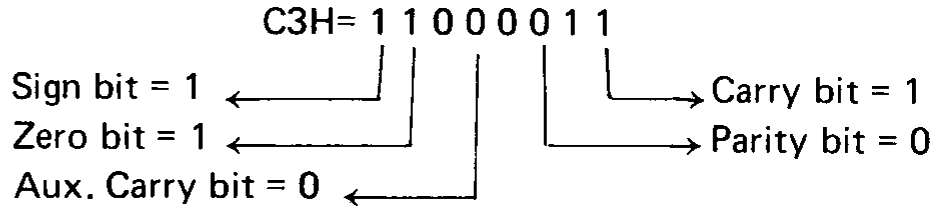
Assume that memory locations 2C00H and 2C01H contain C3H and FFH respectively, and that the stack pointer contains 2C00H. Then the instruction:
POP PSW
will load the accumulator with FFH and set the condition bits as follows:
DAD Double Add
Format:
Label   Code    Operand
oplab:  DAD     rp
                 |
                 +-- B,D,H, or SP
+---+---+-------+---+---+---+---+
| 0 | 0 |   rp  | 1 | 0 | 0 | 1 |
+---+---+-------+---+---+---+---+
rp = 00 for registers B and C
     01 for registers D and E
     10 for registers H and L
     11 for register SP
Description: The 16-bit number in the specified register pair is added to the 16-bit number held in the H and L registers using two’s complement arithmetic. The result replaces the contents of the H and L registers.
Condition bits affected: Carry
Example 1:
Assume that register B contains 33H, register C contains 9FH, register H contains A1H, and register L contains 7BH. Then the instruction:
DAD B
performs the following addition:
  Registers B and C          = 339F
+ Registers H and L          = A17B
                               ----
New contents of H and L      = D51A
Register H now contains D5H and register L now contains 1AH. Since no carry out was produced, the Carry bit is reset = 0.
Example 2:
The instruction:
DAD H
will double the 16-bit number in the H and L registers (which is equivalent to shifting the 16 bits one position to the left).
INX Increment Register Pair
Format:
Label   Code    Operand
oplab:  INX     rp
                 |
                 +-- B,D,H, or SP
+---+---+-------+---+---+---+---+
| 0 | 0 |   rp  | 0 | 0 | 1 | 1 |
+---+---+-------+---+---+---+---+
rp = 00 for registers B and C
     01 for registers D and E
     10 for registers H and L
     11 for register SP
Description: The 16-bit number held in the specified register pair is incremented by one.
Condition bits affected: None
Example:
If registers D and E contain 38H and FFH respectively, the instruction:
INX D
will cause register D to contain 39H and register E to contain 00H.
If the stack pointer SP contains FFFFH, the instruction:
INX SP
will cause register SP to contain 0000H.
DCX Decrement Register Pair
Format:
Label   Code    Operand
oplab:  DCX     rp
                 |
                 +-- B,D,H, or SP
+---+---+-------+---+---+---+---+
| 0 | 0 |   rp  | 1 | 0 | 1 | 1 |
+---+---+-------+---+---+---+---+
rp = 00 for registers B and C
     01 for registers D and E
     10 for registers H and L
     11 for register SP
Description: The 16-bit number held in the specified register pair is decremented by one.
Condition bits affected: None
Example:
If register H contains 98H and register L contains 00H, the instruction:
DCX H
will cause register H to contain 97H and register L to contain FFH.
XCHG Exchange Registers
Format:
Label   Code    Operand
oplab:  XCHG    --
+---+---+---+---+---+---+---+---+
| 1 | 1 | 1 | 0 | 1 | 0 | 1 | 1 |
+---+---+---+---+---+---+---+---+
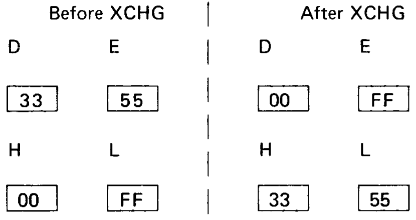
Description: The 16 bits of data held in the H and L registers are exchanged with the 16 bits of data held in the D and E registers.
Condition bits affected: None
Example:
If register H contains 00H, register L contains FFH, register D contains 33H and register E contains 55H, the instruction XCHG will perform the following operation:
XTHL Exchange Stack
Format:
Label   Code    Operand
oplab:  XTHL    --
+---+---+---+---+---+---+---+---+
| 1 | 1 | 1 | 0 | 0 | 0 | 1 | 1 |
+---+---+---+---+---+---+---+---+
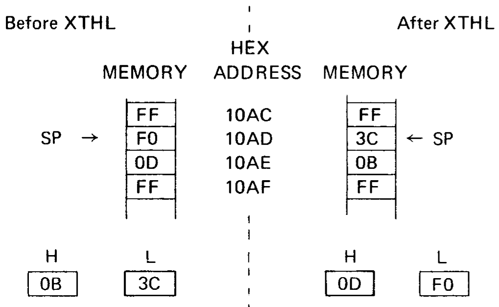
Description: The contents of the L register are exchanged with the contents of the memory byte whose address is held in the stack pointer SP. The contents of the H register are exchanged with the contents of the memory byte whose address is one greater than that held in the stack pointer.
Condition bits affected: None
Example:
If register SP contains 10ADH, registers H and L contain 0BH and 3CH respectively, and memory locations 10ADH and 10AEH contain F0H and 0DH respectively, the instruction XTHL will perform the following operation:
SPHL Load SP From H And L
Format:
Label   Code    Operand
oplab:  SPHL    --
+---+---+---+---+---+---+---+---+
| 1 | 1 | 1 | 1 | 1 | 0 | 0 | 1 |
+---+---+---+---+---+---+---+---+
Description: The 16 bits of data held in the H and L registers replace the contents of the stack pointer SP. The contents of the H and L registers are unchanged.
Condition bits affected: None
Example:
If registers H and L contain 50H and 6CH respectively, the instruction SPHL will load the stack pointer with the value 506CH.
Immediate Instructions
This section describes instructions which perform operations using a byte or bytes of data which are part of the instruction itself.
Instructions in this class occupy two or three bytes as follows:
For the LXI data instruction (3 bytes):
+---+---+-------+---+---+---+---+
| 0 | 0 |   rp  | 0 | 0 | 0 | 1 |
+---+---+-------+---+---+---+---+
|            low data           |
+-------------------------------+
|           high data           |
+-------------------------------+
rp = 00 for registers B and C
     01 for registers D and E
     10 for registers H and L
     11 for register SP
For the MVI data instruction (2 bytes):
+---+---+-----------+---+---+---+
| 0 | 0 |    reg    | 1 | 1 | 0 |
+---+---+-----------+---+---+---+
|              data             |
+-------------------------------+
reg = 000 for register B
      001 for register C
      010 for register D
      011 for register E
      100 for register H
      101 for register L
      110 for memory ref. M
      111 for register A
+---+---+-----------+---+---+---+
| 1 | 1 |     op    | 1 | 1 | 0 |
+---+---+-----------+---+---+---+
|              data             |
+-------------------------------+
op = 000 for ADI
     001 for ACI
     010 for SUI
     011 for SBI
     100 for ANI
     101 for XRI
     110 for ORI
     111 for CPI
The LXI instruction operates on the register pair specified by RP using two bytes of immediate data.
The MVI instruction operates on the register specified by REG using one byte of immediate data. If a memory reference is specified, the instruction operates on the memory location addressed by registers H and L. The H register holds the most significant 8 bits of the address, while the L register holds the least significant 8 bits of the address.
The remaining instructions in this class operate on the accumulator using one byte of immediate data. The result replaces the contents of the accumulator.
The general assembly language instruction format is:
Label   Code    Operand
oplab:  LXI     rp,data
  |              |  |
  |              |  +-- 16-bit data quantity
  |              +----- B, D, H, or SP
  +-------------------- Optional instruction label

- or -

Label   Code    Operand
oplab:  MVI     reg,data
  |              |   |
  |              |   +-- 8-bit data quantity
  |              +------ A,B,C,D,E,H,L, or M
  +--------------------- Optional instruction label

- or -

Label   Code    Operand
oplab:  OP      data
  |      |       |
  |      |       +-- 8-bit data quantity
  |      +---------- ADI,ACI,SUI,SBI,ANI,XRI,ORI,
  |                  or CPI
  +----------------- Optional instruction label
LXI Load Register Pair Immediate
Format:
Label   Code    Operand
oplab:  LXI     rp,data
+---+---+-------+---+---+---+---+
| 0 | 0 |   rp  | 0 | 0 | 0 | 1 |
+---+---+-------+---+---+---+---+
|            low data           |
+-------------------------------+
|           high data           |
+-------------------------------+
Description: The third byte of the instruction (the most significant 8 bits of the 16-bit immediate data) is loaded into the first register of the specified pair, while the second byte of the instruction (the least significant 8 bits of the 16-bit immediate data) is loaded into the second register of the specified pair. If SP is specified as the register pair, the second byte of the instruction replaces the least significant 8 bits of the stack pointer, while the third byte of the instruction replaces the most significant 8 bits of the stack pointer.
Condition bits affected: None
Note
The immediate data for this instruction is a 16-bit quantity. All other immediate instructions require an 8-bit data value.
Example 1:
Assume that instruction label STRT refers to memory location 103H (=259). Then the following instructions will each load the H register with 01H and the L register with 03H:
LXI     H,103H
LXI     H,259
LXI     H,STRT
Example 2:
The following instruction loads the stack pointer with the value 3ABCH:
LXI SP,3ABCH
MVI Move Immediate Data
Format:
Label   Code    Operand
oplab:  MVI     reg,data
+---+---+-----------+---+---+---+
| 0 | 0 |    reg    | 1 | 1 | 0 |
+---+---+-----------+---+---+---+
|              data             |
+-------------------------------+
Description: The byte of immediate data is stored in the specified register or memory byte.
Condition bits affected: None
Example:
Label   Code    Operand         Assembled Data
M1:     MVI     H,3CH           26EC
M2:     MVI     L,0F4H          2EF4
M3:     MVI     M,0FFH          36FF
Todo
The assembled data for M1 is printed as “26EC” in the scan
(scans/page-32.png), but MVI H,3CH assembles to 263C. This looks like a
misprint in the original.
The instruction at M1 loads the H register with the byte of data at M1 +1, i.e., 3CH.
Likewise, the instruction at M2 loads the L register with 0F4H. The instruction at M3 causes the data at M3 + 1 (0FFH) to be stored at memory location 3CF4H. The memory location is obtained by concatenating the contents of the H and L registers into a 16-bit address.
Note
The instructions at M1 and M2 above could be replaced by the single instruction:
LXI H,3CF4H
ADI Add Immediate To Accumulator
Format:
Label   Code    Operand
oplab:  ADI     data
+---+---+---+---+---+---+---+---+
| 1 | 1 | 0 | 0 | 0 | 1 | 1 | 0 |
+---+---+---+---+---+---+---+---+
|              data             |
+-------------------------------+
Description: The byte of immediate data is added to the contents of the accumulator using two’s complement arithmetic.
Condition bits affected: Carry, Sign, Zero, Parity, Auxiliary Carry
Example:
Label   Code    Operand         Assembled Data
AD1:    MVI     A,20            3E14
AD2:    ADI     66              C642
AD3:    ADI     -66             C6BE
The instruction at AD1 loads the accumulator with 14H. The instruction at AD2 performs the following addition:
Accumulator         = 14H = 00010100
AD2 Immediate Data  = 42H = 01000010
                            --------
Result                    = 01010110 = 56H = New accumulator
The parity bit is set. Other status bits are reset.
The instruction at AD3 restores the original contents of the accumulator by performing the following addition:
Accumulator         = 56H  = 01010110
AD3 Immediate Data  = 0BEH = 10111110
                             --------
Result                     = 00010100 = 14H
The Carry, Auxiliary Carry, and Parity bits are set. The Zero and Sign bits are reset.
ACI Add Immediate To Accumulator With Carry
Format:
Label   Code    Operand
oplab:  ACI     data
+---+---+---+---+---+---+---+---+
| 1 | 1 | 0 | 0 | 1 | 1 | 1 | 0 |
+---+---+---+---+---+---+---+---+
|              data             |
+-------------------------------+
Description: The byte of immediate data is added to the contents of the accumulator plus the contents of the carry bit.
Condition bits affected: Carry, Sign, Zero, Parity, Auxiliary Carry
Example:
Label   Code    Operand         Assembled Data
C1:     MVI     A,56H           3E56
C2:     ACI     -66             CEBE
C3:     ACI     66              CE42
Assuming that the Carry bit = 0 just before the instruction at C2 is executed, this instruction will produce the same result as instruction AD3 in the example of Section 3.10.3.
That is:
Accumulator = 14H
Carry       = 1
The instruction at C3 then performs the following addition:
Accumulator         = 14H = 00010100
C3 Immediate Data   = 42H = 01000010
Carry bit           = 1   =        1
                            --------
Result                    = 01010111 = 57H
SUI Subtract Immediate From Accumulator
Format:
Label   Code    Operand
oplab:  SUI     data
+---+---+---+---+---+---+---+---+
| 1 | 1 | 0 | 1 | 0 | 1 | 1 | 0 |
+---+---+---+---+---+---+---+---+
|              data             |
+-------------------------------+
Description: The byte of immediate data is subtracted from the contents of the accumulator using two’s complement arithmetic.
Since this is a subtraction operation, the carry bit is set, indicating a borrow, if there is no carry out of the high-order bit position, and reset if there is a carry out.
Condition bits affected: Carry, Sign, Zero, Parity, Auxiliary Carry
Example:
This instruction can be used as the equivalent of the DCR instruction.
Label   Code    Operand         Assembled Data
        MVI     A,0             3E00
S1:     SUI     1               D601
The MVI instruction loads the accumulator with zero. The SUI instruction performs the following subtraction:
Accumulator          = 0H  = 00000000
-S1 Immediate Data   = -1H = 11111111   two's complement
                             --------
Result                     = 11111111 = -1H
Since there was no carry, and this is a subtract operation, the Carry bit is set, indicating a borrow.
The Zero and Auxiliary Carry bits are also reset, while the Sign and Parity bits are set.
SBI Subtract Immediate from Accumulator With Borrow
Format:
Label   Code    Operand
oplab:  SBI     data
+---+---+---+---+---+---+---+---+
| 1 | 1 | 0 | 1 | 1 | 1 | 1 | 0 |
+---+---+---+---+---+---+---+---+
|              data             |
+-------------------------------+
Description: The Carry bit is internally added to the byte of immediate data. This value is then subtracted from the accumulator using two’s complement arithmetic.
This instruction and the SBB instruction are most useful when performing multibyte subtractions. For an example of this, see the section on Multibyte Addition and Subtraction in Chapter 4.
Since this is a subtraction operation, the carry bit is set if there is no carry out of the high-order position, and reset if there is a carry out.
Condition bits affected: Carry, Sign, Zero, Parity, Auxiliary Carry
Example:
Label   Code    Operand         Assembled Data
        XRA     A               AF
        SBI     1               DE01
The XRA instruction will zero the accumulator (see example earlier in this chapter). If the Carry bit is zero, the SBI instruction will then perform the following operation:
Immediate Data + Carry = 01H
Two's Complement of 01H = 11111111
Adding this to the accumulator produces:
Accumulator = 0H =    00000000
                      11111111
                    ----------
                    0 11111111 = -1H = Result
                    |
                    +--> carry out = 0 causing the Carry bit to be set
The Carry bit is set, indicating a borrow. The Zero and Auxiliary Carry bits are reset, while the Sign and Parity bits are set.
If, however, the Carry bit is one, the SBI instruction will perform the following operation:
Immediate Data + Carry = 02H
Two's Complement of 02H = 11111110
Adding this to the accumulator produces:
Accumulator = 0H =    00000000
                      11111110
                    ----------
                    0 11111110 = -2H = Result
                    |
                    +--> carry out = 0 causing the Carry bit to be set
This time the Carry and sign bits are set, while the zero, parity, and auxiliary Carry bits are reset.
ANI And Immediate With Accumulator
Format:
Label   Code    Operand
oplab:  ANI     data
+---+---+---+---+---+---+---+---+
| 1 | 1 | 1 | 0 | 0 | 1 | 1 | 0 |
+---+---+---+---+---+---+---+---+
|              data             |
+-------------------------------+
Description: The byte of immediate data is logically ANDed with the contents of the accumulator. The Carry bit is reset to zero.
Condition bits affected: Carry, Zero, Sign, Parity
Example:
Label   Code    Operand         Assembled Data
        MOV     A,C             79
A1:     ANI     0FH             E60F
The contents of the C register are moved to the accumulator. The ANI instruction then zeroes the high-order four bits, leaving the low-order four bits unchanged. The Zero bit will be set if and only if the low-order four bits were originally zero.
If the C register contained 3AH, the ANI would perform the following:
Accumulator               = 3AH = 00111010
AND (A1 Immediate Data)   = 0FH = 00001111
                                  --------
Result                          = 00001010 = 0AH
XRI Exclusive-Or Immediate With Accumulator
Format:
Label   Code    Operand
oplab:  XRI     data
+---+---+---+---+---+---+---+---+
| 1 | 1 | 1 | 0 | 1 | 1 | 1 | 0 |
+---+---+---+---+---+---+---+---+
|              data             |
+-------------------------------+
Description: The byte of immediate data is EXCLUSIVE-ORed with the contents of the accumulator. The carry bit is set to zero.
Condition bits affected: Carry, Zero, Sign, Parity
Example:
Since any bit EXCLUSIVE-ORed with a one is complemented, and any bit EXCLUSIVE-ORed with a zero is unchanged, this instruction can be used to complement specific bits of the accumulator. For instance, the instruction:
XRI 81H
will complement the least and most significant bits of the accumulator, leaving the rest unchanged. If the accumulator contained 3BH, the process would work as follows:
Accumulator         = 3BH = 00111011
XRI Immediate data  = 81H = 10000001
                            --------
Result                    = 10111010
ORI Or Immediate With Accumulator
Format:
Label   Code    Operand
oplab:  ORI     data
+---+---+---+---+---+---+---+---+
| 1 | 1 | 1 | 1 | 0 | 1 | 1 | 0 |
+---+---+---+---+---+---+---+---+
|              data             |
+-------------------------------+
Description: The byte of immediate data is logically ORed with the contents of the accumulator.
The result is stored in the accumulator. The Carry bit is reset to zero, while the Zero, Sign, and Parity bits are set according to the result.
Condition bits affected: Carry, Zero, Sign, Parity
Example:
Label   Code    Operand         Assembled Data
        MOV     A,C             79
OR1:    ORI     0FH             F60F
The contents of the C register are moved to the accumulator. The ORI instruction then sets the low-order four bits to one, leaving the high-order four bits unchanged.
If the C register contained 0B5H, the ORI would perform the following:
Accumulator                 = 0B5H = 10110101
OR (OR1 Immediate data)     = 0FH  = 00001111
                                     --------
Result                             = 10111111 = 0BFH
CPI Compare Immediate With Accumulator
Format:
Label   Code    Operand
oplab:  CPI     data
+---+---+---+---+---+---+---+---+
| 1 | 1 | 1 | 1 | 1 | 1 | 1 | 0 |
+---+---+---+---+---+---+---+---+
|              data             |
+-------------------------------+
Description: The byte of immediate data is compared to the contents of the accumulator.
The comparison is performed by internally subtracting the data from the accumulator using two’s complement arithmetic, leaving the accumulator unchanged but setting the condition bits by the result.
In particular, the zero bit is set if the quantities are equal, and reset if they are unequal.
Since a subtract operation is performed, the Carry bit will be set if there is no carry out of bit 7, indicating the immediate data is greater than the contents of the accumulator, and reset otherwise.
Note
If the two quantities to be compared differ in sign, the sense of the Carry bit is reversed.
Condition bits affected: Carry, Zero, Sign, Parity, Auxiliary Carry
Example:
Label   Code    Operand         Assembled Data
        MVI     A,4AH           3E4A
        CPI     40H             FE40
The CPI instruction performs the following operation:
Accumulator             = 4AH =   01001010
+(-Immediate data)      = -40H =  11000000
                                ----------
                                1 00001010 = Result
                                |
                                +--> carry out = 1 causing the Carry bit to be reset
The accumulator still contains 4AH, but the zero bit is reset indicating that the quantities were unequal, and the carry bit is reset indicating DATA is less than the accumulator.
Direct Addressing Instructions
This section describes instructions which reference memory by a two-byte address which is part of the instruction itself. Instructions in this class occupy three bytes as follows:
+---+---+---+-------+---+---+---+
| 0 | 0 | 1 |   op  | 0 | 1 | 0 |
+---+---+---+-------+---+---+---+
|            low add            |
+-------------------------------+
|             hi add            |
+-------------------------------+
op = 10 for STA         low add = least significant 8 bits of a memory address
     11 for LDA         hi add  = most significant 8 bits of a memory address
     00 for SHLD
     01 for LHLD
Note that the address is held least significant byte first.
The general assembly language format is:
Label   Code    Operand
label:  op      exp
  |      |       |
  |      |       +-- A 16-bit memory address
  |      +---------- STA, LDA, SHLD, or LHLD
  +----------------- Optional instruction label
STA Store Accumulator Direct
Format:
Label   Code    Operand
oplab:  STA     adr
+---+---+---+---+---+---+---+---+
| 0 | 0 | 1 | 1 | 0 | 0 | 1 | 0 |
+---+---+---+---+---+---+---+---+
|            low add            |
+-------------------------------+
|             hi add            |
+-------------------------------+
Description: The contents of the accumulator replace the byte at the memory address formed by concatenating HI ADD with LOW ADD.
Condition bits affected: None
Example:
The following instructions will each store the contents of the accumulator at memory address 5B3H:
SAC:    STA     5B3H
        STA     1459
LAB:    STA     010110110011B
LDA Load Accumulator Direct
Format:
Label   Code    Operand
oplab:  LDA     adr
+---+---+---+---+---+---+---+---+
| 0 | 0 | 1 | 1 | 1 | 0 | 1 | 0 |
+---+---+---+---+---+---+---+---+
|            low add            |
+-------------------------------+
|             hi add            |
+-------------------------------+
Description: The byte at the memory address formed by concatenating HI ADD with LOW ADD replaces the contents of the accumulator.
Condition bits affected: None
Example:
The following instructions will each replace the accumulator contents with the data held at location 300H:
LOAD:   LDA     300H
        LDA     3*(16*16)
GET:    LDA     200H+256
SHLD Store H and L Direct
Format:
Label   Code    Operand
oplab:  SHLD    adr
+---+---+---+---+---+---+---+---+
| 0 | 0 | 1 | 0 | 0 | 0 | 1 | 0 |
+---+---+---+---+---+---+---+---+
|            low addr           |
+-------------------------------+
|           high addr           |
+-------------------------------+
Description: The contents of the L register are stored at the memory address formed by concatenating HI ADD with LOW ADD. The contents of the H register are stored at the next higher memory address.
Condition bits affected: None
Example:
If the H and L registers contain AEH and 29H respectively, the instruction:
SHLD 10AH
will perform the following operation:
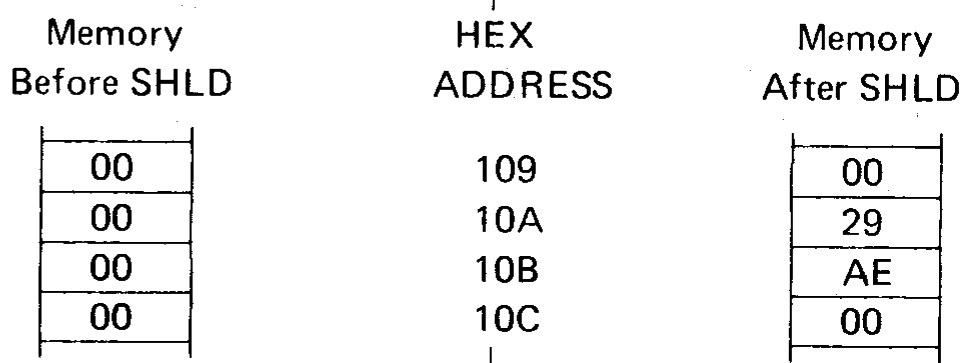
LHLD Load H And L Direct
Format:
Label   Code    Operand
oplab:  LHLD    adr
+---+---+---+---+---+---+---+---+
| 0 | 0 | 1 | 0 | 1 | 0 | 1 | 0 |
+---+---+---+---+---+---+---+---+
| low add |
+-------------------------------+
| hi add |
+-------------------------------+
Description: The byte at the memory address formed by concatenating HI ADD with LOW ADD replaces the contents of the L register. The byte at the next higher memory address replaces the contents of the H register.
Condition bits affected: None
Example:
If memory locations 25BH and 25CH contain FFH and 03H respectively, the instruction:
LHLD 25BH
will load the L register with FFH, and will load the H register with 03H.
Jump Instructions
This section describes instructions which alter the normal execution sequence of instructions. Instructions in this class occupy one or three bytes as follows:
For the PCHL instruction (one byte):
+---+---+---+---+---+---+---+---+ | 1 | 1 | 1 | 0 | 1 | 0 | 0 | 1 | +---+---+---+---+---+---+---+---+
For the remaining instructions (three bytes):
+---+---+---+---+---+---+---+---+ | 1 | 1 | X | X | X | 0 | 1 | X | +---+---+---+---+---+---+---+---+ | low add | +-------------------------------+ | hi add | +-------------------------------+
bit 0 = 1 for JMP, 0 otherwise bits 5-3 = 000 for JMP or JNZ 001 for JZ 010 for JNC 011 for JC 100 for JPO 101 for JPE 110 for JP 111 for JM low add = least significant 8 bits of a memory address hi add = most significant 8 bits of a memory address
Note that, just as addresses are normally stored in memory with the low-order byte first, so are the addresses represented in the Jump instructions.
The three-byte instructions in this class cause a transfer of program control depending upon certain specified conditions. If the specified condition is true, program execution will continue at the memory address formed by concatenating the 8 bits of HI ADD (the third byte of the instruction) with the 8 bits of LOW ADD (the second byte of the instruction). If the specified condition is false, program execution will continue with the next sequential instruction.
The general assembly language format is:
Label Code Operand
oplab: PCHL
| | |
| | +-- not used
+----------------- Optional instruction label
Label Code Operand
label: op EXP
| | |
| | +-- A 16-bit address
| +---------- JMP,JC,JNC,JZ,JNZ,JM,JP,JPE,JPO
+----------------- Optional instruction label
PCHL Load Program Counter
Format:
Label Code Operand
oplab: PCHL --
+---+---+---+---+---+---+---+---+
| 1 | 1 | 1 | 0 | 1 | 0 | 0 | 1 |
+---+---+---+---+---+---+---+---+
Description: The contents of the H register replace the most significant 8 bits of the program counter, and the contents of the L register replace the least significant 8 bits of the program counter. This causes program execution to continue at the address contained in the H and L registers.
Condition bits affected: None
Example 1:
If the H register contains 41H and the L register contains 3EH, the instruction:
PCHL
will cause program execution to continue with the instruction at memory address 413EH.
Example 2:
Arbitrary
Memory Assembled
Address Label Code Operand Data
40C0 ADR: DW LOC 0042
.
4100 STRT: LHLD ADR 2AC040
PCHL E9
.
4200 LOC: NOP 00
Program execution begins at STRT. The LHLD instruction loads registers H and L from locations 40C1H and 40C0H; that is, with 42H and 00H, respectively. The PCHL instruction then loads the program counter with 4200H, causing program execution to continue at location LOC.
JMP JUMP
Format:
Label Code Operand
oplab: JMP adr
+---+---+---+---+---+---+---+---+
| 1 | 1 | 0 | 0 | 0 | 0 | 1 | 1 |
+---+---+---+---+---+---+---+---+
| low add |
+-------------------------------+
| hi add |
+-------------------------------+
Description: Program execution continues unconditionally at memory address adr.
Condition bits affected: None
Example:
Arbitrary
Memory Assembled
Address Label Code Operand Data
3C00 JMP CLR C3003E
3C03 AD: ADI 2 C602
.
3D00 LOAD: MVI A,3 3E03
3D02 JMP 3C03H C3033C
.
3E00 CLR: XRA A AF
3E01 JMP $-101H C3003D
The execution sequence of this example is as follows:
The JMP instruction at 3C00H replaces the contents of the program counter with 3E00H. The next instruction executed is the XRA at CLR, clearing the accumulator. The JMP at 3E01H is then executed.
The program counter is set to 3D00H, and the MVI at this address loads the accumulator with 3. The JMP at 3D02H sets the program counter to 3C03H, causing the ADI instruction to be executed.
From here, normal program execution continues with the instruction at 3C05H.
JC Jump If Carry
Format:
Label Code Operand
oplab: JC adr
+---+---+---+---+---+---+---+---+
| 1 | 1 | 0 | 1 | 1 | 0 | 1 | 0 |
+---+---+---+---+---+---+---+---+
| low add |
+-------------------------------+
| hi add |
+-------------------------------+
Description: If the Carry bit is one, program execution continues at the memory address adr.
Condition bits affected: None
For a programming example, see the section on JPO later in this chapter.
JNC Jump If No Carry
Format:
Label Code Operand
oplab: JNC adr
+---+---+---+---+---+---+---+---+
| 1 | 1 | 0 | 1 | 0 | 0 | 1 | 0 |
+---+---+---+---+---+---+---+---+
| low add |
+-------------------------------+
| hi add |
+-------------------------------+
Description: If the Carry bit is zero, program execution continues at the memory address adr.
Condition bits affected: None
For a programming example see the section on JPO later in this chapter.
JZ Jump If Zero
Format:
Label Code Operand
oplab: JZ adr
+---+---+---+---+---+---+---+---+
| 1 | 1 | 0 | 0 | 1 | 0 | 1 | 0 |
+---+---+---+---+---+---+---+---+
| low add |
+-------------------------------+
| hi add |
+-------------------------------+
Description: If the zero bit is one, program execution continues at the memory address adr.
Condition bits affected: None
JNZ Jump If Not Zero
Format:
Label Code Operand
oplab: JNZ adr
+---+---+---+---+---+---+---+---+
| 1 | 1 | 0 | 0 | 0 | 0 | 1 | 0 |
+---+---+---+---+---+---+---+---+
| low add |
+-------------------------------+
| hi add |
+-------------------------------+
Description: If the Zero bit is zero, program execution continues at the memory address adr.
Condition bits affected: None
JM Jump If Minus
Format:
Label Code Operand
oplab: JM adr
+---+---+---+---+---+---+---+---+
| 1 | 1 | 1 | 1 | 1 | 0 | 1 | 0 |
+---+---+---+---+---+---+---+---+
| low add |
+-------------------------------+
| hi add |
+-------------------------------+
Description: If the Sign bit is one (indicating a negative result), program execution continues at the memory address adr.
Condition bits affected: None
JPE Jump If Parity Even
Format:
Label Code Operand
oplab: JPE adr
+---+---+---+---+---+---+---+---+
| 1 | 1 | 1 | 0 | 1 | 0 | 1 | 0 |
+---+---+---+---+---+---+---+---+
| low add |
+-------------------------------+
| hi add |
+-------------------------------+
Description: If the parity bit is one (indicating a result with even parity), program execution continues at the memory address adr.
Condition bits affected: None
JPO Jump If Parity Odd
Format:
Label Code Operand
oplab: JPO adr
+---+---+---+---+---+---+---+---+
| 1 | 1 | 1 | 0 | 0 | 0 | 1 | 0 |
+---+---+---+---+---+---+---+---+
| low add |
+-------------------------------+
| hi add |
+-------------------------------+
Description: If the Parity bit is zero (indicating a result with odd parity), program execution continues at the memory address adr.
Condition bits affected: None
Examples of jump instructions:
This example shows three different but equivalent methods for jumping to one of two points in a program based upon whether or not the Sign bit of a number is set. Assume that the byte to be tested is in the C register.
Assembled
Label Code Operand Data
ONE: MOV A,C 79
ANI 80H E680
JZ PLUS CAXXXX
JNZ MINUS C2XXXX
TWO: MOV A,C 79
RLC 07
JNC PLUS D2XXXX
JMP MINUS C3XXXX
THREE: MOV A,C 79
ADI 0 C600
JM MINUS FAXXXX
PLUS: SIGN BIT RESET
.
MINUS: SIGN BIT SET
The AND immediate instruction in block ONE zeroes all bits of the data byte except the Sign bit, which remains unchanged. If the Sign bit was zero, the Zero condition bit will be set, and the JZ instruction will cause program control to be transferred to the instruction at PLUS. Otherwise, the JZ instruction will merely update the program counter by three, and the JNZ instruction will be executed, causing control to be transferred to the instruction at MINUS. (The Zero bit is unaffected by all jump instructions).
The RLC instruction in block TWO causes the Carry bit to be set equal to the Sign bit of the data byte. If the Sign bit was reset, the JNC instruction causes a jump to PLUS. Otherwise the JMP instruction is executed, unconditionally transferring control to MINUS. (Note that, in this instance, a JC instruction could be substituted for the unconditional jump with identical results).
The add immediate instruction in block THREE causes the condition bits to be set. If the sign bit was set, the JM instruction causes program control to be transferred to MINUS. Otherwise, program control flows automatically into the PLUS routine.
Call Subroutine Instructions
This section describes the instructions which call subroutines. These instructions operate like the jump instructions, causing a transfer of program control. In addition, a return address is pushed onto the stack for use by the RETURN instructions (see Return From Subroutine Instructions later in this chapter).
Instructions in this class occupy three bytes as follows:
+---+---+---+---+---+---+---+---+
| 1 | 1 | X | X | X | 1 | 0 | X |
+---+---+---+---+---+---+---+---+
| low add |
+-------------------------------+
| hi add |
+-------------------------------+
bit 0 = 1 for CALL, 0 otherwise
bits 5-3 = 000 for CNZ
001 for CZ or CALL
010 for CNC
011 for CC
100 for CPO
101 for CPE
110 for CP
111 for CM
low add = least significant 8 bits of a memory address
hi add = most significant 8 bits of a memory address
Note that, just as addresses are normally stored in memory with the low-order byte first, so are the addresses represented in the call instructions.
The general assembly language instruction format is:
Label Code Operand
label: op sub
| | |
| | +-- A 16-bit memory address
| +---------- CALL,CC,CNC,CZ,CNZ,CM,CP,CPE,CPO
+----------------- Optional instruction label
Instructions in this class call subroutines upon certain specified conditions. If the specified condition is true, a return address is pushed onto the stack and program execution continues at memory address SUB, formed by concatenating the 8 bits of HI ADD with the 8 bits of LOW ADD. If the specified condition is false, program execution continues with the next sequential instruction.
CALL Call
Format:
Label Code Operand
oplab: CALL sub
+---+---+---+---+---+---+---+---+
| 1 | 1 | 0 | 0 | 1 | 1 | 0 | 1 |
+---+---+---+---+---+---+---+---+
| low add |
+-------------------------------+
| hi add |
+-------------------------------+
Description: A call operation is unconditionally performed to subroutine sub.
Condition bits affected: None
For programming examples see Chapter 4.
CC Call If Carry
Format:
Label Code Operand
oplab: CC sub
+---+---+---+---+---+---+---+---+
| 1 | 1 | 0 | 1 | 1 | 1 | 0 | 0 |
+---+---+---+---+---+---+---+---+
| low add |
+-------------------------------+
| hi add |
+-------------------------------+
Description: If the Carry bit is one, a call operation is performed to subroutine sub.
Condition bits affected: None
For programming examples using subroutines, see Chapter 4.
CNC Call If No Carry
Format:
Label Code Operand
oplab: CNC sub
+---+---+---+---+---+---+---+---+
| 1 | 1 | 0 | 1 | 0 | 1 | 0 | 0 |
+---+---+---+---+---+---+---+---+
| low add |
+-------------------------------+
| hi add |
+-------------------------------+
Description: If the Carry bit is zero, a call operation is performed to subroutine sub.
Condition bits affected: None
For programming examples using subroutines, see Chapter 4.
CZ Call If Zero
Format:
Label Code Operand
oplab: CZ sub
+---+---+---+---+---+---+---+---+
| 1 | 1 | 0 | 0 | 1 | 1 | 0 | 0 |
+---+---+---+---+---+---+---+---+
| low add |
+-------------------------------+
| hi add |
+-------------------------------+
Description: If the Zero bit is zero, a call operation is performed to subroutine sub.
Condition bits affected: None
For programming examples using subroutines, see Chapter 4.
Todo
The CZ and CNZ descriptions are transcribed as printed
(scans/page-41.png), but the original has them swapped. CZ actually
calls when the Zero bit is one, and CNZ when it is zero (compare
JZ/JNZ and RZ/RNZ). Consider adding an erratum note for readers.
CNZ Call If Not Zero
Format:
Label Code Operand
oplab: CNZ sub
+---+---+---+---+---+---+---+---+
| 1 | 1 | 0 | 0 | 0 | 1 | 0 | 0 |
+---+---+---+---+---+---+---+---+
| low add |
+-------------------------------+
| hi add |
+-------------------------------+
Description: If the Zero bit is one, a call operation is performed to subroutine sub.
Condition bits affected: None
For programming examples using subroutines, see Chapter 4.
CM Call If Minus
Format:
Label Code Operand
oplab: CM sub
+---+---+---+---+---+---+---+---+
| 1 | 1 | 1 | 1 | 1 | 1 | 0 | 0 |
+---+---+---+---+---+---+---+---+
| low add |
+-------------------------------+
| hi add |
+-------------------------------+
Description: If the Sign bit is one (indicating a minus result), a call operation is performed to subroutine sub.
Condition bits affected: None
For programming examples using subroutines, see Chapter 4.
CP Call If Plus
Format:
Label Code Operand
oplab: CP sub
+---+---+---+---+---+---+---+---+
| 1 | 1 | 1 | 1 | 0 | 1 | 0 | 0 |
+---+---+---+---+---+---+---+---+
| low add |
+-------------------------------+
| hi add |
+-------------------------------+
Description: If the Sign bit is zero (indicating a positive result), a call operation is performed to subroutine sub.
Condition bits affected: None
For programming examples using subroutines, see Chapter 4.
CPE Call If Parity Even
Format:
Label Code Operand
oplab: CPE sub
+---+---+---+---+---+---+---+---+
| 1 | 1 | 1 | 0 | 1 | 1 | 0 | 0 |
+---+---+---+---+---+---+---+---+
| low add |
+-------------------------------+
| hi add |
+-------------------------------+
Description: If the Parity bit is one (indicating even parity), a call operation is performed to subroutine sub.
Condition bits affected: None
For programming examples using subroutines, see Chapter 4.
Todo
In the scan, the CPE bit diagram labels both address bytes “low add”. This transcription uses “low add / hi add” to match every other instruction.
CPO Call If Parity Odd
Format:
Label Code Operand
oplab: CPO sub
+---+---+---+---+---+---+---+---+
| 1 | 1 | 1 | 0 | 0 | 1 | 0 | 0 |
+---+---+---+---+---+---+---+---+
| low add |
+-------------------------------+
| hi add |
+-------------------------------+
Description: If the Parity bit is zero (indicating odd parity), a call operation is performed to subroutine sub.
Condition bits affected: None
For programming examples using subroutines, see Chapter 4.
Return From Subroutine Instructions
This section describes the instructions used to return from subroutines. These instructions pop the last address saved on the stack into the program counter, causing a transfer of program control to that address.
Instructions in this class occupy one byte as follows:
+---+---+---+---+---+---+---+---+
| 1 | 1 | X | X | X | 0 | 0 | X |
+---+---+---+---+---+---+---+---+
bit 0 = 1 for RET, 0 otherwise
bits 5-3 = 000 for RNZ
001 for RZ or RET
010 for RNC
011 for RC
100 for RPO
101 for RPE
110 for RP
111 for RM
The general assembly language instruction format is:
Label Code Operand
oplab: op
| | |
| | +-- not used
| +---------- RET,RC,RNC,RZ,RNZ,RM,RP,RPE,RPO
+----------------- Optional statement label
Instructions in this class perform RETURN operations upon certain specified conditions. If the specified condition is true, a return operation is performed. Otherwise, program execution continues with the next sequential instruction.
Todo
The OCR of scans/page-42.png was badly jumbled, and the “110 for RP”
line was missing. The table above is reconstructed; check it against the
scan.
RET Return
Format:
Label Code Operand
oplab: RET --
+---+---+---+---+---+---+---+---+
| 1 | 1 | 0 | 0 | 1 | 0 | 0 | 1 |
+---+---+---+---+---+---+---+---+
Description: A return operation is unconditionally performed.
Thus, execution proceeds with the instruction immediately following the last call instruction.
Condition bits affected: None
RC Return If Carry
Format:
Label Code Operand
oplab: RC --
+---+---+---+---+---+---+---+---+
| 1 | 1 | 0 | 1 | 1 | 0 | 0 | 0 |
+---+---+---+---+---+---+---+---+
Description: If the Carry bit is one, a return operation is performed.
Condition bits affected: None
For programming examples, see Chapter 4.
RNC Return If No Carry
Format:
Label Code Operand
oplab: RNC --
+---+---+---+---+---+---+---+---+
| 1 | 1 | 0 | 1 | 0 | 0 | 0 | 0 |
+---+---+---+---+---+---+---+---+
Description: If the carry bit is zero, a return operation is performed.
Condition bits affected: None
For programming examples, see Chapter 4.
RZ Return If Zero
Format:
Label Code Operand
oplab: RZ --
+---+---+---+---+---+---+---+---+
| 1 | 1 | 0 | 0 | 1 | 0 | 0 | 0 |
+---+---+---+---+---+---+---+---+
Description: If the Zero bit is one, a return operation is performed.
Condition bits affected: None
For programming examples, see Chapter 4.
RNZ Return If Not Zero
Format:
Label Code Operand
oplab: RNZ --
+---+---+---+---+---+---+---+---+
| 1 | 1 | 0 | 0 | 0 | 0 | 0 | 0 |
+---+---+---+---+---+---+---+---+
Description: If the Zero bit is zero, a return operation is performed.
Condition bits affected: None
For programming examples, see Chapter 4.
RM Return If Minus
Format:
Label Code Operand
oplab: RM --
+---+---+---+---+---+---+---+---+
| 1 | 1 | 1 | 1 | 1 | 0 | 0 | 0 |
+---+---+---+---+---+---+---+---+
Description: If the Sign bit is one (indicating a minus result), a return operation is performed.
Condition bits affected: None
For programming examples, see Chapter 4.
RP Return If Plus
Format:
Label Code Operand
oplab: RP --
+---+---+---+---+---+---+---+---+
| 1 | 1 | 1 | 1 | 0 | 0 | 0 | 0 |
+---+---+---+---+---+---+---+---+
Description: If the Sign bit is zero (indicating a positive result), a return operation is performed.
Condition bits affected: None
For programming examples, see Chapter 4.
RPE Return If Parity Even
Format:
Label Code Operand
oplab: RPE --
+---+---+---+---+---+---+---+---+
| 1 | 1 | 1 | 0 | 1 | 0 | 0 | 0 |
+---+---+---+---+---+---+---+---+
Description: If the Parity bit is one (indicating even parity), a return operation is performed.
Condition bits affected: None
For programming examples, see Chapter 4.
RPO Return If Parity Odd
Format:
Label Code Operand
oplab: RPO --
+---+---+---+---+---+---+---+---+
| 1 | 1 | 1 | 0 | 0 | 0 | 0 | 0 |
+---+---+---+---+---+---+---+---+
Description: If the Parity bit is zero (indicating odd parity), a return operation is performed.
Condition bits affected: None
For programming examples, see Chapter 4.
RST Instruction
This section describes the RST (restart) instruction, which is a special purpose subroutine jump. This instruction occupies one byte.
Format:
Label Code Operand
oplab: RST exp
+---+---+-----------+---+---+---+
| 1 | 1 | exp | 1 | 1 | 1 |
+---+---+-----------+---+---+---+
Note
“exp” must evaluate to a number in the range 000B to 111B.
Description: The contents of the program counter are pushed onto the stack, providing a return address for later use by a RETURN instruction.
Program execution continues at memory address:
0000000000EXP000B
Normally, this instruction is used in conjunction with up to eight eight-byte routines in the lower 64 words of memory in order to service interrupts to the processor. The interrupting device causes a particular RST instruction to be executed, transferring control to a subroutine which deals with the situation as described in Section 6.
A RETURN instruction then causes the program which was originally running to resume execution at the instruction where the interrupt occurred.
Condition bits affected: None
Example:
Label Code Operand Comment
RST 10-7 ; Call the subroutine at
; address 24 (011000B)
RST E SHL 1 ; Call the subroutine at
; address 48 (110000B). E
; is equated to 11B.
RST 8 ; Invalid instruction
RST 3 ; Call the subroutine at
; address 24 (011000B)
For detailed examples of interrupt handling, see Chapter 5.
Interrupt Flip-Flop Instructions
This section describes the instructions which operate directly upon the Interrupt Enable flip-flop INTE. Instructions in this class occupy one byte as follows:
+---+---+---+---+---+---+---+---+
| 1 | 1 | 1 | 1 | X | 0 | 1 | 1 |
+---+---+---+---+---+---+---+---+
X = 1 for EI, 0 for DI
The general assembly language format is:
Label Code Operand
label: op
| | |
| | +-- not used
| +---------- EI or DI
+----------------- Optional instruction label
EI Enable Interrupts
Format:
Label Code Operand
oplab: EI --
+---+---+---+---+---+---+---+---+
| 1 | 1 | 1 | 1 | 1 | 0 | 1 | 1 |
+---+---+---+---+---+---+---+---+
Description: This instruction sets the INTE flip-flop, enabling the CPU to recognize and respond to interrupts.
Condition bits affected: None
DI Disable Interrupts
Format:
Label Code Operand
oplab: DI --
+---+---+---+---+---+---+---+---+
| 1 | 1 | 1 | 1 | 0 | 0 | 1 | 1 |
+---+---+---+---+---+---+---+---+
Description: This instruction resets the INTE flip-flop, causing the CPU to ignore all interrupts.
Condition bits affected: None
Input/Output Instructions
This section describes the instructions which cause data to be input to or output from the 8080. Instructions in this class occupy two bytes as follows:
+---+---+---+---+---+---+---+---+
| 1 | 1 | 0 | 1 | X | 0 | 1 | 1 |
+---+---+---+---+---+---+---+---+
| exp |
+-------------------------------+
X = 1 for IN, 0 for OUT
exp = 8-bit device number
The device number is a hardware characteristic of the input or output device, not under the programmer’s control.
The general assembly language format is:
Label Code Operand
label: op exp
| | |
| | +-- An 8-bit device number
| +---------- IN or OUT
+----------------- Optional instruction label
IN Input
Format:
Label Code Operand
oplab: IN exp
+---+---+---+---+---+---+---+---+
| 1 | 1 | 0 | 1 | 1 | 0 | 1 | 1 |
+---+---+---+---+---+---+---+---+
| exp |
+-------------------------------+
Description: An eight-bit data byte is read from input device number exp and replaces the contents of the accumulator.
Condition bits affected: None
Example:
Label Code Operand Comment
IN 0 ; Read one byte from input
; device # 0 into the
; accumulator
IN 10/2 ; Read one byte from input
; device # 5 into the
; accumulator
OUT Output
Format:
Label Code Operand
oplab: OUT exp
+---+---+---+---+---+---+---+---+
| 1 | 1 | 0 | 1 | 0 | 0 | 1 | 1 |
+---+---+---+---+---+---+---+---+
| exp |
+-------------------------------+
Description: The contents of the accumulator are sent to output device number exp.
Condition bits affected: None
Example:
Label Code Operand Comment
OUT 10 ; Write the contents of the
; accumulator to output
; device # 10
OUT 1FH ; Write the contents of the
; accumulator to output
; device # 31
HLT Halt Instruction
This section describes the HLT instruction, which occupies one byte.
Format:
Label Code Operand
oplab: HLT
|
+-- not used
+---+---+---+---+---+---+---+---+
| 0 | 1 | 1 | 1 | 0 | 1 | 1 | 0 |
+---+---+---+---+---+---+---+---+
Description: The program counter is incremented to the address of the next sequential instruction. The CPU then enters the STOPPED state and no further activity takes place until an interrupt occurs.
Pseudo-Instructions
This section describes pseudo-instructions recognized by the assembler. A pseudo-instruction is written in the same fashion as the machine instructions described earlier in this chapter, but does not cause any object code to be generated. It acts merely to provide the assembler with information to be used subsequently while generating object code.
The general assembly language format of a pseudo-instruction is:
Label Code Operand
name op opnd
| | |
| | +-- Operand, may be optional
| +---------- ORG,EQU,SET,END,IF,ENDIF,MACRO,
| ENDM
+----------------- name may be required, option, or illegal
Note
Names on pseudo-instructions are not followed by a colon, as are labels. Names are required in the label field of MACRO, EQU, and SET pseudo-instructions. The label fields of the remaining pseudo-instructions may contain optional labels, exactly like the labels on machine instructions. In this case, the label refers to the memory location immediately following the last previously assembled machine instruction.
ORG Origin
Format:
Label Code Operand
oplab: ORG exp
|
+-- A 16-bit address
Description: The assembler’s location counter is set to the value of exp, which must be a valid 16-bit memory address. The next machine instruction or data byte(s) generated will be assembled at address exp, exp+1, etc.
If no ORG appears before the first machine instruction or data byte in the program, assembly will begin at location 0.
Example 1:
Hex Memory Assembled
Address Label Code Operand Data
ORG 1000H
1000 MOV A,C 79
1001 ADI 2 C602
1003 JMP NEXT C35010
HERE: ORG 1050H
1050 NEXT: XRA A AF
The first ORG pseudo-instruction informs the assembler that the object program will begin at memory address 1000H. The second ORG tells the assembler to set its location counter to 1050H and continue assembling machine instructions or data bytes from that point. The label HERE refers to memory location 1006H, since this is the address immediately following the jump instruction. Note that the range of memory from 1006H to 104FH is still included in the object program, but does not contain assembled data. In particular, the programmer should not assume that these locations will contain zero, or any other value.
Example 2:
The ORG pseudo-instruction can perform a function equivalent to the DS (define storage) instruction (see the section on DS earlier in this chapter). The following two sections of code are exactly equivalent:
Memory Assbl.
Address Label Code Operand Label Code Operand Data
2C00 MOV A,C MOV A,C 79
2C01 JMP NEXT JMP NEXT C3102C
2C04 DS 12 ORG $+12
2C10 NEXT: XRA A NEXT: XRA A AF
EQU Equate
Format:
Label Code Operand
name EQU exp
| |
| +-- An expression
+----------------- Required name
Description: The symbol “name” is assigned the value by EXP by the assembler. Whenever the symbol “name” is encountered subsequently in the assembly, this value will be used.
Note
A symbol may appear in the name field of only one EQU pseudo-instruction; i.e., an EQU symbol may not be redefined.
Example:
Label Code Operand Assembled Data
PTO EQU 8
OUT PTO D308
The OUT instruction in this example is equivalent to the statement:
OUT 8
If at some later time the programmer wanted the name PTO to refer to a different output port, it would be necessary only to change the EQU statement, not every OUT statement.
SET
Format:
Label Code Operand
name SET exp
| |
| +-- An expression
+----------------- Required name
Description: The symbol “name” is assigned the value of exp by the assembler. Whenever the symbol “name” is encountered subsequently in the assembly, this value will be used unless changed by another SET instruction.
This is identical to the EQU equation, except that symbols may be defined more than once.
Example 1:
Label Code Operand Assembled Data
IMMED SET 5
ADI IMMED C605
IMMED SET 10H-6
ADI IMMED C60A
Example 2:
Before every assembly, the assembler performs the following SET statements:
Label Code Operand
B SET 0
C SET 1
D SET 2
E SET 3
H SET 4
L SET 5
M SET 6
A SET 7
If this were not done, a statement like:
MOV D,A
would be invalid, forcing the programmer to write:
MOV 2,7
END End Of Assembly
Format:
Label Code Operand
oplab: END --
Description: The END statement signifies to the assembler that the physical end of the program has been reached, and that generation of the object program and (possibly) listing of the source program should now begin.
One and only one END statement must appear in every assembly, and it must be the (physically) last statement of the assembly.
IF AND ENDIF Conditional Assembly
Format:
Label Code Operand
oplab: IF exp
|
+-- an expression
.
. statements
.
oplab: ENDIF --
Description: The assembler evaluates exp. If exp evaluates to zero, the statements between IF and ENDIF are ignored. Otherwise the intervening statements are assembled as if the IF and ENDIF were not present.
Example:
Label Code Operand Assembled Data
COND SET 0FFH
IF COND
MOV A,C 79
ENDIF
.
COND SET 0
IF COND
MOV A,C
ENDIF
XRA C A9
MACRO AND ENDM Macro Definition
Format:
Label Code Operand
name MACRO list
| |
| +-- A list of expressions,
| normally ASCII constants
+----------------- Required name
.
. statements
.
oplab: ENDM
Description: For a detailed explanation of the definition and use of macros, together with programming examples, see Chapter 3.
The assembler accepts the statements between MACRO and ENDM as the definition of the macro named “name.” Upon encountering “name” in the code field of an instruction, the assembler substitutes the parameters specified in the operand field of the instruction for the occurrences of “list” in the macro definition, and assembles the statements.
Note
The pseudo-instruction MACRO may not appear in the list of statements between MACRO and ENDM; i.e., macros may not define other macros.
Comment Field
The only rule governing this field is that it must begin with a semicolon (;).
A comment field may appear alone on a line: